Showing posts with label level control. Show all posts

Point and Continuous Level Sensors in Food Processing: Ensuring Quality, Safety, and Efficiency

Point and Continuous Level Sensors in Food Processing

Maintaining precise control over ingredient levels and product quantities in the food processing industry is crucial for ensuring consistent quality, safety, and efficiency. Point and continuous-level sensors play a vital role in achieving these goals by providing accurate measurements and real-time monitoring of various substances throughout production. These sensors find applications in inventory management, overfill protection, waste management, and regulatory control.

When selecting level sensors for food processing applications, it is essential to consider the importance of 3A-certified probes. The 3A Sanitary Standards, developed by the 3-A Sanitary Standards, Inc., set strict guidelines for the design and materials used in equipment that comes into direct contact with food products. By choosing 3A-certified probes, food processors can ensure that their level sensors meet the highest standards of hygiene and cleanability, preventing contamination and ensuring the safety of the final product.

Level control sensors are invaluable tools for inventory management in food processing facilities. By continuously monitoring the levels of ingredients, such as liquids, powders, and solids, in storage tanks and silos, these sensors provide real-time data that helps optimize stock levels and prevent shortages. This information enables food processors to streamline their supply chain, reduce waste, and minimize production downtime caused by insufficient raw materials.

Overfill protection is another critical application of level sensors in food processing. By installing point-level sensors at strategic locations within storage vessels and processing tanks, food processors can detect when the product level reaches a predetermined maximum threshold. These sensors trigger alarms or automatically shut off filling processes, preventing costly and potentially hazardous spills. Overfill protection safeguards against product loss and helps maintain a safe working environment for employees.

Level sensors also contribute to food processing facilities' effective waste management and regulatory control. By accurately monitoring the levels of waste products, such as wastewater or byproducts, food processors can ensure that these substances are correctly handled and disposed of in compliance with environmental regulations. Additionally, level sensors can help food processors meet stringent food safety regulations by precisely measuring ingredient quantities and ensuring that products meet the required specifications.

In conclusion, point and continuous level sensors are indispensable tools in the food processing industry, enabling manufacturers to maintain the highest quality, safety, and efficiency standards. By utilizing 3A-certified probes, implementing level control for inventory management, and leveraging level sensors for overfill protection, waste management, and regulatory power, food processors can optimize their operations and deliver consistently superior products to consumers.

Piping Specialties / PSI Controls
https://psi-team.com
800-223-1468

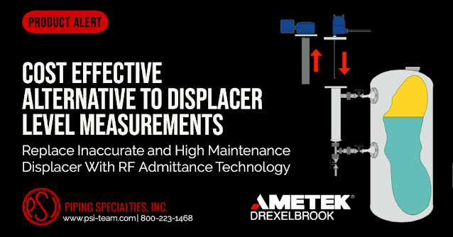
Replace Inaccurate and High Maintenance Displacer Level Controls With RF Admittance Technology

Replace Inaccurate and High Maintenance Displacer Level

 Cost Effective Alternative to Displacer Level Measurements

THE PROBLEM

  • Displacer accuracy is dependent on the specific gravity of a fluid. Varying specific gravities and “off spec” product result in significant measurement errors.
  • Coating build-up on the displacer body produces errors.
  • “Blowdowns” to clean displacer internals and cages is time consuming and expensive.
  • Rebuilds due to component wear add significantly to the total cost of ownership.
  • Interface measurements are more sensitive to slight specific gravity variances and result in separator throughput lower than the design specification.

THE SOLUTION

  • AMETEK Drexelbrook Radio Frequency (RF) Admittance technology eliminates all of the inherent problems with Displacer technology level measurement.
  • RF is immune to changes in specific gravity, density, temperature, and pressure.
  • Accuracies to 1⁄4 inch of level in short span installations.
  • No moving parts to wear, No periodic maintenance.
  • Replacement cost differentials covered by eliminating one rebuild.

Piping Specialties / PSI Controls
https://psi-team.com
800-223-1468


The AMETEK Drexelbrook Impulse Guided Wave Radar Level Transmitter

Drexelbrook Impulse

The Drexelbrook Impulse is a guided wave radar (TDR) that measures all liquids and slurries' overall level and other volumetric measures. When competitive water sensors fail, the Impulse continues to provide accurate values. 

The Drexelbrook Impulse is a two-wire guided wave radar that uses field-proven TDR level (Time Domain Reflectometry) technology to produce accurate Total Level, Distance, and Volumetric outputs on all liquids and slurries. 

The Impulse handles even the most challenging level measuring applications. It will continue to give dependable and accurate measurements even in the presence of disturbances such as agitated or uneven surfaces, foam, or probe coating. Changes in the density and dielectric characteristics, dusts, mist, and turbulence do not affect it. When other water level sensors fail, the Impulse continues to measure. 

This water level sensor is a perfect replacement for costly mechanical dispenser systems, with a wide range of probe types and material possibilities for various applications. 

This guided wave radar is simple to use for any user due to its simple navigation, push-button setups, and HART connections. It only takes a few minutes to install. Choose your level measuring type and language, and the Impulse is ready to use. 

The Impulse guided wave radar is intrinsically safe, explosion-proof, and non-incendive, and it does not require calibration or level changes.

Additionally, Drexelbrook recently introduced an enlarged coaxial sensor for The Impulse GWR. The new 1.66" (42mm) diameter probe provides reliable accuracy within high viscosity liquids. The new enlarged coaxial sensor option for The Impulse GWR allows the material to flow off the sensor easily when used with viscous fluids.

Piping Specialties / PSI Controls
https://psi-team.com
800-223-1468

Setting Up and Calibrating the Drexelbrook MultiPoint II Level Switch


This video demonstrates how to calibrate and set the Drexelbrook MultiPoint II level switch.

The Drexelbrook Multipoint II level switch product offers three control points located anywhere along a single vertically inserted level sensing element. This level switch can be used to provide high level, high-high level, and low level control points. It also provides an adjustable differential feature for one of the control points for pump on/pump off control making it ideal for sump level control. It is designed to be intrinsically safe for Class I Groups A,B,C,D and Class II Groups E,F,G (Div. 1 and 2). The unit is mounted in FM approved explosion proof housing. The MultiPoint II has no moving parts and the need for maintenance is therefore eliminated. The Drexelbrook MultiPoint II is an economical solution for processes requiring multiple operating points.

For more information about level instrumentation, contact Piping Specialties, Inc. / PSI Controls by calling 800-223-1468 or visit their web site at https://psi-team.com.

Plugged Chute Detection for Granular Materials

Intellipoint RF Admittance Plugged Chute Detector
Detecting plugs in granular material conveying chutes is difficult due to the heavy, abrasive materials and dusty, coating nature of the environment. Many technologies used to detect material movement in chutes have considerable downside. For instance, regulatory requirements and source disposal problems make nuclear gauges an unappealing choice, insertion type sensors are quickly damaged by falling material, microwave sensors require two mounting windows to operate, and vibrating chute walls can damage electrical components.

A better alternative is the Drexelbrook Intellipoint RF Admittance Plugged Chute Detector. Its design allows for the reliable detection of a plugged chute, reducing costly downtime and material spill over.

The Drexelbrook plugged chute detector, also known as a blocked chute switch, reliably detects the presence or absence of bulk solids material flowing through chutes in an economical way without sacrificing flow speed. If process material stops flowing due to a plugged condition, the flush mounted capacitance sensing element will alarm, allowing further action to occur (alerting an operator, shutting down a conveyor belt, etc.). The Cote shield circuitry ignores even heavy coatings, and the flush mounted sensing element does not interfere with material flow. There are no moving parts to wear or jam, and thus, it requires virtually no maintenance. In fact, the Intellipoint Mean Time To Failure (MTTF) is calculated to more than 110 years!

There are no regulatory requirements with the adoption of the Intellipoint, and system electronics can be mounted remotely to eliminate vibration concerns. Due to the rugged sensor design this point level switch is ideal for coal, wood chips, ores and powders. This point level switch automatically recognizes and ignores coatings to prevent false alarms and, as it is flush mounted through a chute wall, nothing protrudes into the chute to interfere with or obstruct material flow.

Choosing the Intellipoint provides reliable detection of plugged chutes that will keep your plant running smoothly and virtually eliminates spills occurring due to plugged conditions.

Key Features
  • Curved and flat sensors are available
  • DPDT relay dry contacts at 5A, 120VAC
  • Less maintenance than other technologies; no moving parts to hang up or wear out
  • Uses Drexelbrook PML series electronics
  • Supply voltage: 19-250 VAC, 18-200 VDC, Auto-detecting without jumpers
For more information, contact Piping Specialties, Inc. by calling 800-223-1468 or by visiting https://psi-team.com.

Problems with Measuring Level of High Density Pulp Stock

Level Measurement in Pulp Stock
Level Measurement in Pulp Stock has posed problems for a wide range of level measurement technologies. In most pulp mills this is the most challenging application on site.

The environment in the high-density pulp tank is very corrosive to most common metals and the clouds of dense steam vapors that rise from the stock and foaming surface of the level are a constant source of signal loss for many non-contact technologies.

Due to the size of the vessel and density of the stock, mechanical devices are typically short  lived.Stock coatings that form on all interior surfaces add additional mechanical stress and the pulp coating deposits can adversely affect accurate level measurement performance.

One of the challenges of a level measurement device is to control the level in the stock tank, thereby helping to control the average pulp density by controlling the speed of the pump.The response time of the level measurement system is critical in controlling the pump speed and reducing pump oscillations and surges that will eventually reduce the life of the pump.Too slow of a response from the level instrument will allow the level to rise above it ’s optimum density level and cause excessive loading and wear on the pump.


Piping Specialties, Inc.
PSI Controls
https://psi-team.com
800-223-1468


Drexelbrook’s ThePoint™ Series Point Level Switch: Settings, Adjustments, and Changing Calibration Modes

The AMETEK Drexelbrook ThePoint™ Series uses No-Cal™ technology to detect the presence or absence of material without calibration or initiation via setpoint adjustments, push-buttons or magnets.

ThePoint™ level measurement switch features both Auto-Cal and manual calibration. The standard Auto-Calibration mode is applicable to most liquid and slurry point level measurements. If preferred, the manual calibration can be used and is recommended for some application. ThePoint electronic unit has auto and manual calibration modes built into the standard unit and can be accessed through the simple routine shown in the video below. The inclusion of these calibration modes allows the Drexelbrook RF Point Level Products application flexibility that is far greater than any other point level product on the market. ThePoint™ level switch can be used in Liquids, Solids, Slurries, and Interface applications.

To learn more specific instructions on the (8) calibration modes ThePoint™ has available, download the "Drexelbrook ThePoint Series Point Level Switch Installation and Operating Instructions" from this link.


Continuous and Point Level Control Selection Guide

Drexelbrook Continuous and Point Level Control
Drexelbrook Continuous and Point Level Control Products
Based on experience from of thousands of inquiries about level measurement, most questions boil down to "What is the best level measurement instrument for my application? That depends on quite a few application considerations, such as:
  • Will the measured media add coating to the probe?
  • Can the probe have contact with the media?
  • Are there explosion hazards?
  • What is the physical type of application, well, tank, open channel or floating roof tank?
This document can help deliver the perfect continuous level transmitter or level switches for your application.

Download a PDF version of the Drexelbrook Continuous and Point Level Control Selection Guide here, or view the embedded document below.

https://psi-team.com
800-223-1468

What is a Magnetic Level Gauge?

Magnetic Level Gauge
Magnetic Level Gauge (Penberthy)
Magnetic level gauges, also known as magnetic level indicators, are routinely used to provide a display of liquid level in tanks and other vessels. Their popularity stems from their high visibility from distances and non-invasive design which reduces the possibility of points and the risks of fugitive emissions.

"Mag Gauge" construction is fairly simple. A magnetic float, designed for the specific gravity of the material being measured, rides inside a vertical pipe on top of the process media. A gauge with magnetically coupled visual indicator is fastened to the pipe. As the media inside the pipe rises and falls, the visual indicator moves in the same fashion.

Magnetic level gauges are often employed in tandem with magnetostrictive, guided wave radar, or other measurement means to provide a reliable local display of liquid level, as well as an electrical signal that can be transmitted to recording instrumentation or controllers.

Magnetic level gauges features:
  • Continuous level measurement
  • Operable without electric power
  • Direct visual tank fluid level indication, regardless of tank shape or profile.
  • Wide range of operating temperature and pressure
  • Breakage resistant construction
  • Range of construction materials available to accommodate corrosive media
  • Measuring indicators, switches, and transmitters mounted externally, without contacting the medium being measured.
  • Low maintenance operation.
  • Readable level indication from greater distance than glass sight gauges.
  • Applicable to large fluid level ranges with a single instrument.
Magnetic level indicators are used widely in liquid level measurement and should be considered as a candidate for fulfilling those applications where the magnetic level gauge features fulfill the project requirements. There are many options available to customize the level indicator for each specific application. Share your application challenges with a product specialist, combining your process knowledge with their product application expertise to develop an effective solution.

Understanding Guided Wave Radar Level Instruments

Guided Wave Radar (GWR) level transmitter
Guided Wave Radar (GWR)
level transmitter (Drexelbrook)
One of several technologies used for level measurement in process control is guided wave radar. A Guided Wave Radar (GWR) level transmitter combines time domain reflectometry (TDR), equivalent time sampling (ETS), and low power circuitry with a form factor that includes a wave guide extending into the contained media. TDR measures distance or level using pulses of electromagnetic energy. The pulse travels along the waveguide until it reaches the media surface and is reflected back to the unit. The speed of the pulse is known, so an accurate measure of the travel time for the signal can be processed into a distance measurement. Different media will produce a range of amplitude in the reflection, with a greater dielectric difference between air and target medium producing higher amplitude in the reflection. Industries, such as telephone, computer, and power transmission, have relied on TDR for years in order to detect and pinpoint breaks in wires or cables, making the technology more mature than it may appear by its limited timeline in level measurement applications.

ETS is used to measure the high speed, low power electromagnetic energy, and is typical when applying TDR to level measurement technology, where the signal travel distance and time are very short. The electromagnetic signals are captured by the ETS technology in nanoseconds, and are then reconstructed in the equivalent time of milliseconds. The radar scans the waveguide, collecting thousands of samples to be used in signal processing. Integrating both technologies into a single level transmitter yields an accurate and responsive instrument for process measurement.

GWR instrumentation is useful in the process control industry for its ability to measure levels in a quick, consistent way. GWR transmitters are contact radar level measurement tools, as opposed to pulsed non-contact radar transmitters that emit radar pulses through free air without a waveguide. Probes, inserted into the subject tank or vessel, serve as the waveguide for the pulsed signal. They guide the pulsed microwave vertically into the tank, providing a measure of immunity from disturbance by the tank and surrounding media. Guided wave radar technology differs from non-contact radar in a number of ways. The presence or absence of a probe is only one of them.

GWR level transmitters are used in process measurement applications throughout many industries, such as food and beverage. Tanks, pumps, and piping systems for both storage and transport can utilize GWR to continuously monitor levels. Other vessels, such as reduction, forming, mixing, heating, cooking, and cooling, can utilize GWR for similar reasons. Additionally, other stages of food and beverage manufacturing, such as centrifugation and decontamination, can be good fits for GWR technology. Guided wave radarĂ­s previous applicability in industries aside from liquid processing and implementation in a wide range of process settings show the flexibility and reliability of GWR technology.

Selecting the best level measurement technology for an application can be a challenge. Share your project requirements and concerns with a process instrumentation specialist, combining your own process knowledge and experience with their product application expertise to develop effective solutions.

Understanding Hydrostatic Pressure

Hydrostatic level transmitter
(Drexelbrook)
Pressure measurement is an inferential way to determine the height of a column of liquid in a vessel in process control. The vertical height of the fluid is directly proportional to the pressure at the bottom of the column, meaning the amount of pressure at the bottom of the column, due to gravity, relies on a constant to indicate a measurement. Regardless of whether the vessel is shaped like a funnel, a tube, a rectangle, or a concave polygon, the relationship between the height of the column and the accumulated fluid pressure is constant. Weight density depends on the liquid being measured, but the same method is used to determine the pressure.

A common method for measuring hydrostatic pressure is a simple gauge. The gauge is installed at the bottom of a vessel containing a column of liquid and returns a measurement in force per unit area units, such as PSI. Gauges can also be calibrated to return measurement in units representing the height of liquid since the linear relationship between the liquid height and the pressure. The particular density of a liquid allows for a calculation of specific gravity, which expresses how dense the liquid is when compared to water. Calculating the level or depth of a column of milk in a food and beverage industry storage vessel requires the hydrostatic pressure and the density of the milk. With these values, along with some constants, the depth of the liquid can be calculated.

The liquid depth measurement can be combined with known dimensions of the holding vessel to calculate the volume of liquid in the container. One measurement is made and combined with a host of constants to determine liquid volume. The density of the liquid must be constant in order for this method to be effective. Density variation would render the hydrostatic pressure measurement unreliable, so the method is best applied to operations where the liquid density is known and constant.

Interestingly, changes in liquid density will have no effect on measurement of liquid mass as opposed to volume as long as the area of the vessel being used to store the liquid remains constant. If a liquid inside a vessel that’s partially full were to experience a temperature increase, resulting in an expansion of volume with correspondingly lower density, the transmitter will be able to still calculate the exact mass of the liquid since the increase in the physical amount of liquid is proportional to a decrease in the liquid’s density. The intersecting relationships between the process variables in hydrostatic pressure measurement demonstrate both the flexibility of process instrumentation and how consistently reliable measurements depend on a number of process related factors.

Visit PSI-Team.com for more information on pressure and level instrumentation.

Level Measurement Technologies Provide Accurate Level Control & Ignore Foams in Filler Bowl Applications

Filler Bowl Applications
RF Admittance and Magnetostrictive technologies have a proven performance record in gravity feed flow control for the dispensing of liquids into bottles or containers.

In high speed bottling operations many different filling methods can be used depending on the nature of the product and type of container being filled. For many Food and Beverage, and Pharmaceutical applications the preferred filling method is by using level measurements to control the gravity ow of liquids into bottles or containers from the filler bowl. The level measurement method is very consistent with liquids and slurries to prevent over-filling or under-filling of a bottle or container by keeping a consistent product level in the filler bowl. 

Level filling is the oldest filling method and is still largely favored in specific markets. This is largely due to products being sold in translucent containers. The consumer expects to see that all containers are filled to the same precise level and will reject a container with a level lower than others on the shelf. 

Filler Bowl ApplicationsIn a gravity feed filler bowl, the natural head pressure of the liquid is used to ll each bottle. The liquid level in the filler bowl must be kept at a constant level so the pressure within the filler bowl remains constant. This permits each bottle or container to ll to the correct level in the same amount of time. 

The Problem: 

Hydrostatic pressure level measurement systems, which have been traditionally used for this application, are found to have errors in level measurements when changing from one process material to the next, which usually has a slightly different specific gravity. As the process fluid’s specific gravity is changed, this leads to either an over- ll or under- ll condition. 

The Solution: 

AMETEK-Drexelbrook provides sanitary 3A approved systems in both RF Admittance and Magnetostrictive technologies for use in filler bowl measurements that remain unaffected by changes in specific gravity, changes in temperature or changes in pressure or vacuum. Both technologies can provide the accuracies that are required for reliable performance in the face of light or heavy liquid viscosities, foaming conditions, and have the ability to ignore process coatings that may develop on the sanitary sensors. The sensors are of rugged construction and will not be affected by the shock or vibration of the bottling process. 

RF Admittance systems are supplied with a Triclover fitting with a rigid Teflon coated sensor the length of the measurement range. Accuracy is ±1% of measured span. Systems are agency approved as intrinsically safe for Class I, Div. 1 hazardous installations. RF Admittance has the ability to measure a wide range of process materials and ignore most foam and process build-up on the sensor. Systems are powered by a two-wire, 24Vdc power source. 

Magnetostrictive systems are supplied with a Triclover fitting and use a 240 grit finished 316SS rigid sensor and oat. Accuracy is 0.1% of measured span. Systems are agency approved as intrinsically safe for Class I, Div. 1 hazardous installations. Magnetostrictive systems can easily ignore foaming conditions as the oat will sink through the foam and rest on the liquid surface. Systems are powered by a two-wire, 24Vdc power source. 

AMETEK-Drexelbrook systems can provide analog 4-20 mA, HART, or Honeywell DE outputs. Sensor lengths can be as small as a few inches to over 10 ft. All systems are maintenance free and can be easily con gured without complex calibration. 

AMETEK-Drexelbrook has successfully supplied filler bowl level measurement systems to many major Food & Beverage and Pharmaceutical customers over the past 40 years and have hundreds of successful applications on products such as milk, fruit and vegetable juices, jellies, baby foods, soups, beer, spirits, ground meat, pet foods, sodas, and more.