Showing posts with label Maine. Show all posts

Advanced Valve Assemblies for Liquid and Gas Venting and Safety Shut-Off Operations

Advanced Valve Assemblies for Liquid and Gas Venting and Safety Shut-Off Operations

FM classes 7400, 7412, 7420, and 7422 are standards and certifications established by FM Global, a large insurance company emphasizing loss prevention services. Each class specifies particular requirements for equipment and systems used in industrial and commercial settings. These classifications are part of FM Global's comprehensive approach to ensuring safety and reliability in equipment and systems related to fire protection and risk reduction.

A-T Controls manufactures FM-approved valve assemblies for liquid and gas vents and safety shut-off requirements. These valve assemblies have received FM approval, certifying their suitability for applications that demand protective measures for fuel-burning equipment by FM classes 7400, 7412, 7420, and 7422. Each assembly comprises a spring return automated ball valve, an explosion-proof limit switch, and a solenoid pilot valve. Customers can choose from two designs for the valves: a 3-piece design, which offers options for threaded, socket weld, or butt weld end connections, and a flanged design, available in ASME Class 150 and 300. These valves come in sizes from 1/4 inch to 6 inches. The assemblies are at the forefront of quarter-turn automation technology, featuring a rack and pinion actuator. In synergy with the assembly's superior valve seating and stem seal design, this actuator ensures reliable and consistent closure and venting as required. These assemblies offer a compact, efficient solution for fuel gas safety shut-off or venting systems.

For more information, contact Piping Specialties, Inc., a premier New England-based company specializing in the specification and support of industrial valves. At the heart of their expertise lies a deep understanding of valves, which are crucial to ensuring industrial safety and operational efficiency. PSI is a team of seasoned professionals who excel in selecting the most suitable valves for various industrial applications. From initial consultation and specification to after-sales service, PSI ensures every valve operates at its best, safeguarding processes and personnel.

Piping Specialties, Inc. is a trusted ally committed to delivering excellence in industrial valves in an industry where precision and dependability are non-negotiable.

Piping Specialties / PSI Controls
https://psi-team.com
800-223-1468


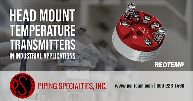
Maximizing Accuracy and Efficiency: The Benefits of Using Head Mount Temperature Transmitters in Industrial Applications

Maximizing Accuracy and Efficiency: The Benefits of Using Head Mount Temperature Transmitters in Industrial Applications

A head mount temperature transmitter is crucial in industrial control instrumentation, particularly in processes where precise temperature measurement and control are essential. The transmitter is mounted directly on or near the temperature sensor in the sensor housing, in the protective enclosure known as a "connection head" or "thermowell head." The transmitter fits into or onto this head, making it a part of the sensor assembly. Here's a detailed description of its functionality and value:

Functionality
  • Temperature Sensing: The primary function of a head mount temperature transmitter is to sense temperature and connect with a temperature sensor, such as a thermocouple or a Resistance Temperature Detector (RTD).
  • Signal Conversion: The transmitter converts the raw signal from the sensor into a standardized signal, usually a 4-20 mA current signal, although it can also be a digital signal like HART, Foundation Fieldbus, or PROFIBUS.
  • Signal Isolation and Amplification: These transmitters isolate and amplify the signal for more accurate and reliable readings, essential in industrial environments where electrical noise or long transmission distances could affect signal integrity.
  •  Local Mounting: As the name suggests, head mount transmitters are mounted directly on or near the sensor, typically in the connection head of the temperature sensor. This proximity minimizes signal degradation that can occur over long distances.
Value in Industrial Applications
  • Accuracy and Stability: By converting the signal close to the sensor, head mount transmitters reduce potential errors and losses in signal transmission, leading to more accurate and stable measurements.
  • Reduced Wiring Costs: Wiring requirements are simple, reducing installation and maintenance costs because of the standardized signal.
  • Improved Noise Immunity: Proximity minimizes the impact of electrical noise, which is especially valuable in industrial environments with high electromagnetic interference.
  • Ease of Integration: Standardized output signals make integrating these transmitters into a wide range of control and data acquisition systems easier.
  • Environmental Protection: Many head mount transmitters come with robust, weatherproof enclosures, making them suitable for harsh industrial environments.
  • Flexibility and Scalability: They offer flexibility regarding sensor types and signal outputs, making them adaptable to various applications and scalable for future expansions or modifications in the process control system.
In summary, head-mount temperature transmitters play a pivotal role in industrial control systems by enhancing temperature measurements' accuracy, reliability, and efficiency. Their integration into process control systems provides significant value in terms of operational stability, cost efficiency, and adaptability to various industrial environments.

Piping Specialties / PSI Controls
https://psi-team.com
800-223-1468

Industrial Open Air Radar Transmitters Powered by FMCW Technology

Industrial Open Air Radar Transmitters Powered by FMCW Technology

Basic Understanding of Radar


Radar (Radio Detection and Ranging) is a system that uses electromagnetic waves to identify the range, altitude, direction, or speed of both moving and fixed objects such as aircraft, ships, motor vehicles, weather formations, and terrain. It transmits a signal, bouncing off the target and returning to the radar system. By analyzing the reflected signal, the radar can determine various parameters about the target.


FMCW (Frequency Modulated Continuous Wave)


When discussing FMCW, we are talking about a specific type of radar signal. Here's how FMCW works:


  1. Continuous Wave (CW): Traditional radar systems emit a brief pulse of radio energy and then wait for that pulse to reflect off an object and return. In contrast, Continuous Wave radar emits a constant signal or wave.
  2. Frequency Modulation (FM): In FMCW radar, the frequency of the continuous wave signal is varied or modulated over time. This can be done linearly, where the frequency increases or decreases at a constant rate or in other patterns.


The benefit of FMCW is that the frequency change provides a way to determine the range (distance to an object). There's a delay when the transmitted wave bounces off an object and returns. During this time, the transmitted wave's frequency has changed. By comparing the received wave's frequency to the current transmitted frequency, the radar system can determine how long it took for the wave to return and thus calculate the distance to the object.


FMCW radar is handy because it can be more compact, requires less peak transmit power (because it's continuous wave and not pulsed), and can provide range and speed information simultaneously.


Open Air Radar Transmitters


"Open air" in the context of radar transmitters usually refers to systems that operate without waveguides or enclosed transmission mediums. Instead, they transmit their signals directly into the environment. These systems are used in various applications, including vehicle radars (like those used in adaptive cruise control or autonomous vehicles), weather radars, and more.


Summary:


An open-air radar transmitter that uses FMCW is a radar system that transmits a continuous wave signal directly into the environment, modulating the signal's frequency over time. By analyzing the frequency shift of the returned signal relative to the transmitted signal, the radar can determine the range to the reflecting object. This technology is widely utilized due to its efficiency, compactness, and ability to provide detailed information about detected objects.


Drexelbrook's open-air radar products deliver exceptional resolution and accuracy tailored for demanding applications. These instruments harness FMCW (Frequency Modulated Continuous Wave) technology, ensuring a powerful signal at the measurement surface. This robustness guarantees optimal return signals, even when measuring agitated liquids.


A Drexelbrook radar level transmitter stands out as the optimal choice for applications that necessitate non-contact technology.


For more information about Drexelbrook level instruments in New England, contact Piping Specialties / PSI Controls. Call 800-223-1468 or visit https://psi-team.com.

Advanced Water Level Monitoring in Sewage Pools

Advanced Water Level Monitoring in Sewage Pools

The complex sewage system of a power plant necessitates immediate maintenance and management. The water utilized for operating turbines and other waste materials runs through the sewage system, and ultimately to the municipal wastewater treatment facility.

Some treatment pools are located in isolated areas around the plant, making it challenging for maintenance staff to access and repair damage promptly. Plant maintenance personnel continually look for ways to more effectively manage the pools and avoid situations where wastewater could overflow.

With the sewage system linked to a central control room, data from each sewage pool has to be transmitted to the primary Distributed Control System (DCS). To achieve optimal management of the sewers, continuous monitoring and attendants are usually necessary.

Technicians understand that sewer blockages inevitably lead to wastewater flooding due to the time required for the equipment to address the backup. This flooding results in significant damage to the surrounding area. Hence, it is crucial to regulate the wastewater level in the pools to prevent such incidents from occurring.

An outstanding solution for this problem is to install two Drexelbrook USonic continuous level transmitters to monitor level in the sewage pools. The USonic's capability to deliver contactless, continuous, and precise water level readings in the pools provide engineers with a comprehensive understanding of the pools' condition. The device's compact size and integral design facilitate easy installation, enabling a quick and efficient solution. With a measuring range of up to 30 feet, the USonic effortlessly provides water level readings of the 12-foot-high sewage pools. Its scan distance function can identify obstacles in the pool and record interfering signals. The USonic connects to the central control system via a 4-20mA interface, granting the engineers constant oversight of the water levels in the sewers, ensuring that the sewers would maintain the appropriate water level and the system would receive a notification in the event of an emergency.

For more information about the use of Drexelbrook USonic level transmitters in New England, contact:

Piping Specialties / PSI Controls
800-223-1468

Plugged Chute Detection Technology: The Superiority of RF Admittance

The Best Plugged Chute Detection Technology: The Superiority of RF Admittance

The operation of industrial processes is a delicate balance of efficiency, safety, and maintenance. A crucial part of maintaining this balance is ensuring the smooth operation of material handling systems, which often employ chutes to transport bulk materials. One common complication these systems face is the problem of chute blockages or plugging, a critical issue that can lead to costly downtime, equipment damage, and potential safety hazards.


Plugged chute detection technologies mitigate these challenges, offering early detection and warning of chute blockages. However, the effectiveness of these technologies varies, and understanding their characteristics is essential for making an informed decision.


Overview of Plugged Chute Detection Technologies

Plugged chute detection technologies fall into three broadly classified groups, mechanical, acoustic, and electromagnetic methods.


Mechanical systems, such as tilt switches and paddle wheel indicators, are simple and inexpensive but prone to mechanical failure and false alarms due to vibration or material buildup. They also require regular maintenance to function effectively.


Acoustic detectors, on the other hand, utilize microphones to listen for changes in the acoustic signature of material flow. While this can be an effective method, it is sensitive to environmental noise and requires sophisticated signal processing to distinguish between normal and blocked flow.


Electromagnetic methods include capacitive probes, microwave radar, and RF Admittance. These offer non-contact detection and are less prone to false alarms and mechanical failures—however, the material's properties, environmental conditions, and installation setup affect their performance and application.


RF Admittance: The Optimal Choice

After an extensive review of these technologies, RF Admittance emerges as the overall best selection for plugged chute detection for several reasons:


Reliability

RF Admittance technology uses a probe to measure changes in the dielectric constant (a property of materials that affects their response to an electric field) between the sensor and the chute wall. When the chute is clear, the admittance (the measure of how easily a circuit or device allows an electric current to pass) between the probe and chute wall will be at one level, and when the chute is blocked, the admittance will change significantly. This reliable detection method leads to fewer false alarms than mechanical and acoustic systems.


Resistance to Material Buildup

One of the significant advantages of RF Admittance technology is its resistance to material buildup on the probe. The technology uses a driven shield construction that ensures only the material near the active sensor affects the reading. This feature helps to eliminate the risk of false alarms due to material buildup, a common issue in other technologies.


Versatility

RF Admittance technology works with various materials, regardless of their conductive or non-conductive properties, making it a versatile solution in different industries handling multiple types of bulk materials.


The Drexelbrook Solution


The Drexelbrook Plugged Chute Detector consistently identifies whether material is flowing through chutes. If the material ceases to flow due to a blockage, an alarm from the flush-mounted capacitance sensing element will be triggered, prompting further necessary actions such as notifying an operator or shutting down a conveyor belt.


The Drexelbrook detector, also known as a blocked chute switch, reliably tracks the presence or absence of bulk solids material in chutes without compromising flow speed. This cost-effective device ensures the continuous flow of materials.


Its robust sensor design makes this point-level switch optimal for handling materials such as coal, wood chips, ores, and powders. Since it is flush mounted through a chute wall, there is no protrusion into the chute to hinder or obstruct material flow.


The point-level switch can automatically identify and disregard coatings, thus preventing false alarms. It features a universal power supply that auto-detects and adjusts to the input power source.


Unlike similar technologies, the point-level switch for detecting plugged chutes permits remote electronics installation at a convenient or safer location.


The dependable detection of plugged chutes ensures smooth plant operations and significantly reduces the chance of spills due to blockages.


Key Features:

  • Availability of both curved and flat sensors
  • DPDT relay dry contacts rated at 5A, 120VAC
  • Requires less maintenance compared to other technologies; devoid of any moving parts that could potentially hang up or wear out
  • Utilizes Drexelbrook PML series electronics
  • Auto-detecting supply voltage range: 19-250 VAC, 18-200 VDC, without the need for jumpers

For more information, contact:
Piping Specialties, Inc.
https://psi-team.com
800-223-1468

The Emerson TESCOM™ Anderson Greenwood H2 Series for Hydrogen Applications and Fuel Stations

The Emerson TESCOM™ Anderson Greenwood H2 Series for Hydrogen Applications and Fuel Stations

Hydrogen Fuel Stations are specialized refueling infrastructure that provides hydrogen gas for fuel cell vehicles (FCVs). These stations store and dispense hydrogen in a compressed or liquefied form, which is then used by FCVs to generate electricity through a chemical reaction with oxygen in a fuel cell stack, thus powering the vehicle.

There has been increasing interest and investment in hydrogen fuel stations and fuel cell technology across the country, driven by the goals of reducing emissions, increasing energy security, and diversifying the energy mix. Federal and state governments, private companies, and research institutions have collaborated to support developing and deploying hydrogen fuel stations and related technologies.

To boost the growth of hydrogen fuel stations, the US Department of Energy (DOE) initiated the H2@Scale initiative to advance hydrogen production, storage, distribution, and utilization technologies. This program seeks to lower hydrogen costs, increase its output from various sources (including renewables), and facilitate its adoption in multiple sectors, such as transportation, industry, and power generation.

Emerson's TESCOM™ Anderson Greenwood Instrumentation Valves H2 Series are high-pressure gas applications valves for hydrogen fueling stations and function as isolation valves. 

The H2 Valve Series employs stem seal technology, enabling consistent pressure containment and low operating torque, making it well-suited for hydrogen fuel dispensing systems. By offering a reliable, low-maintenance solution, the H2 Valve Series allows manufacturers and integrators of hydrogen fueling stations to reduce operational service expenses and potential leakage. 

The H2 Series complies with the ISO 19880.3 standard for 700 bar H70 Station Rating in hydrogen fuel station applications. Its compact, lightweight, and ergonomic design enhances installation and operational processes.


For more information, contact:
Piping Specialties, Inc.
800-223-1468

Level Measurement in the Food Processing Industry

Level Measurement in the Food Processing Industry

Level sensors and controls are crucial in industrial food processing and production facilities to ensure quality and consistency. These devices monitor and regulate the level of liquids, solids, or granular materials in containers, vessels, or silos. Here are some of the most common types of level sensors and controls used in the industry:


  1. Capacitive level sensors: These sensors detect changes in capacitance caused by the presence or absence of material (liquid or solid) in a container. They measure liquids, powders, or granular materials levels in various applications, including food and beverages.
  2. Ultrasonic level sensors: Ultrasonic sensors use sound waves to measure the distance between the sensor and the material's surface. These sensors are non-contact and used for measuring levels of liquids or solids in tanks or silos and provide the food industry with accuracy and reliability.
  3. Radar level sensors: Similar to ultrasonic sensors, radar level sensors use radio waves to measure the distance between the sensor and the material's surface. They are also non-contact and suitable for liquid and solid materials. Radar sensors are particularly useful in challenging environments with dust, vapor, or foam, making them ideal for food processing applications.
  4. Hydrostatic pressure level sensors: These sensors measure the pressure exerted by the liquid column on the sensor at a specific depth. The pressure re-calibrates to a level measurement. They are primarily used for measuring liquid levels in tanks and have broad use in the food and beverage industry.
  5. Float level sensors: Float sensors use a floating device to detect the liquid level in a container. The float's vertical or tilting movement triggers a mechanical or electrical signal indicating the liquid level. Food processing plants often use them for simple and cost-effective level measurements.
  6. Vibrating or tuning fork level sensors: These sensors use a vibrating probe or tuning fork that changes its vibration frequency when it comes into contact with a material. They can detect the presence or absence of material and provide point-level detection of liquids, powders, or granular materials.
  7. Optical level sensors: Optical sensors use infrared or visible light to detect the presence or absence of a material at a specific level. They are suitable for various materials, including liquids, powders, and solids, in food processing applications where minimum contact with the material is essential.


The choice of level sensor and control system depends on factors like the process material, the required accuracy, the process conditions, and the specific application within the food processing facility. Each technology has advantages and limitations, so careful consideration is needed to select the most suitable option for each application.


For more information, contact:
Piping Specialties, Inc.

800-223-1468

Process Refractometers - The Vaisala Polaris™ Product Family

The Vaisala Polaris Process Refractometers

Industrial refractometers are essential in process automation as they help ensure product quality and consistency, reduce waste, and increase productivity. Refractometers measure a substance's refractive index, which measures how much light is bent as it passes through a sample. This measurement can provide valuable information about the composition and concentration of a solution, which is critical in many industrial processes.

In the food and beverage industry, refractometers measure the sugar content of juices, jams, and other products. This measurement helps ensure that the products are consistent in taste and texture and meet regulatory requirements. In the pharmaceutical industry, refractometers measure the concentration of active ingredients in medications, which is critical for ensuring the effectiveness and safety of the product. In pulp and paper production, process refractometers measure the concentration of dissolved solids in different stages of the production process, such as in the pulping process, bleaching process, or paper coating process. Process refractometers are used in semiconductor manufacturing to measure the concentration of chemical solutions used in various functions, such as cleaning, etching, and chemical mechanical planarization. Finally, process refractometers are commonly used in chemical production to measure the concentration of dissolved solids, such as salts, acids, and other chemicals, in various stages of the production process. 

By automating the process of measuring refractive index, industrial refractometers can provide accurate and reliable measurements in real-time without the need for manual testing, helping to reduce errors and improve process efficiency, as well as reduce labor costs associated with manual testing. In addition, automated refractometers can be integrated into larger process control systems, allowing for continuous monitoring and control of critical process parameters.

Vaisala specializes in developing and manufacturing environmental and industrial measurement equipment and systems. Their new Vaisala Polaris™ Product Family optimizes manufacturing processes, enhances productivity, and saves resources, energy, and time in various industries and hundreds of applications.

Vaisala Polaris™ utilizes an optical measurement principle that eliminates the need for regular maintenance when combined with zero moving parts, making their product an efficient and reliable solution for businesses needing continuous, uninterrupted measurement readings. Additionally, Polaris™ works seamlessly out of the box with Vaisala's Indigo520 transmitters, allowing for an easy setup process. To further ensure accuracy, Vaisala has developed a library of over 500 concentration models that allow for precise measurements of various dissolved solids, catering to the unique needs of their clients.

Vaisala Polaris™ boasts unparalleled accuracy, with no chance of drift due to the absence of particles, bubbles, or color influencing the readings. Additionally, Polaris™ product has long-term stability, and the measurement principle involves no moving parts, ensuring years, and even decades, of precise and stable measurement. As an added benefit, Vaisala provides an Engineer to Order service for more significant opportunities, allowing for the customization of their product to fit the specific needs of their clients.

Overall, industrial refractometers play a critical role in process automation, helping to ensure product quality and consistency, improve efficiency and productivity, and reduce waste and costs. As automation technology advances, refractometers and other process monitoring instruments will likely become even more important in industrial settings. Vaisala Polaris™ is an advanced technology that provides superior performance and is ideal for your application. For more information about Vaisala Polaris™ in New England, contact Piping Specialties / PSI Controls. Call them at 800-223-1468 or visit https://psi-team.com.

Trunnion Mount Valves

Trunnion Mount Valves

Trunnion mount valves are a type of industrial valve used to control the flow of fluids, such as liquids, gases, and slurries, in high-pressure systems. The term "trunnion mount" refers to how the valve mounts on a trunnion, a cylindrical projection that serves as a pivot point for the valve.

The valve body is typically made of metal, such as cast iron, steel, or stainless steel, and may be lined with materials such as PTFE or rubber to improve corrosion resistance and reduce wear. The valve stem, the part of the valve that rotates to open and close the valve, is also usually made of high-strength metal.

One of the most common uses of trunnion mount valves is in oil and gas production and transportation. These valves are often used in pipelines to control the flow of crude oil, natural gas, and other hydrocarbons. They are also commonly used in chemical plants, power plants, and other industrial facilities to control the flow of fluids in high-pressure systems.

Due to the need for tight shutoff and precise flow control, trunnion mount valves are typically used in high-pressure systems operating at 600 psi or higher pressures. They are also designed to handle high-pressure differential applications and are operated manually, pneumatically, or electrically.

Habonim designs and manufactures high-pressure ball valves and valve automation packages specially built for safety, endurance, and reliability to cover gases and fluids control up to 1,000 bar (15,000psi). 

The Habonim valve series is for harsh conditions in oil & gas and petrochemical industries, for underground and above-ground installation. Its robust design can withstand heavy loads from large sizes, high pressures, and dynamic temperature cycles. 

The trunnion valve series is certified to API 6D (Habonim monogram #6D-1278) with a valve wall thickness that is in full compliance with ANSI B16.34. The trunnion valve line withstands the maximum differential pressure rating specified by the American National Standards Institute (ANSI). The product range offers a range of end connectors, providing design flexibility and customized to meet each customer's specific needs and preferences.

For more information, contact:
Piping Specialties, Inc.
800-223-1468

The Role of Metal Expansion Joints

Metal Expansion Joints

Expansion joints, also known as bellows or compensators, are flexible connectors that are used in process and HVAC piping systems to absorb movements, such as thermal expansion and contraction, vibration, and misalignment. They are designed to prevent damage to the piping system, equipment, and surrounding structures by allowing for the movement and stress that occurs within the system.

There are several types of expansion joints, including metallic, non-metallic, and fabric. Metallic expansion joints are made of metal bellows and are typically used in high-pressure and high-temperature applications, as well as in applications that require a high degree of corrosion resistance. These expansion joints are typically made of stainless steel, but they can also be made of other metals such as Inconel, Monel, and Hastelloy.

The main function of metallic expansion joints is to provide flexibility in the piping system. They do this by allowing for movement in three main ways:
  • Lateral movement: Metallic expansion joints can accommodate lateral movement, which is movement in a side-to-side direction. This is important in systems that are subjected to thermal expansion and contraction, as the pipes will expand and contract due to temperature changes.
  • Angular movement: Metallic expansion joints can also accommodate angular movement, which is movement in a rotational direction. This is important in systems that are subjected to vibration, as the pipes will vibrate due to the flow of fluid or gas.
  • Axial movement: Metallic expansion joints can also accommodate axial movement, which is movement in a back-and-forth direction. This is important in systems that are subjected to misalignment, as the pipes may not be perfectly aligned.
  • In addition to providing flexibility, metallic expansion joints also help to reduce noise and vibration, and they can protect against the effects of corrosion, erosion, and abrasion. They are often used in a variety of industries, including power generation, petrochemical, pharmaceutical, and food and beverage.
If you'd like to discuss applying metal expansion joints in your application, contact:

Piping Specialties, Inc.
800-223-1468

Cryogenic Ball Valves

Cryogenic Ball Valves

Cryogenic ball valves are a type of valve that is designed to function at extremely low temperatures, typically below -150°C. They are used in a variety of applications where low temperature fluids need to be controlled, such as in the storage, transport, and processing of cryogenic gases, such as liquid nitrogen, oxygen, and argon.

Cryogenic ball valves are equipped with special materials and features that enable them to operate effectively at such low temperatures. For example, the body of the valve may be made from materials such as stainless steel or aluminum that have low temperature properties, and the valve may be equipped with a special insulation material to prevent heat transfer from the environment to the valve. The ball and seat of the valve may also be made from materials such as tungsten carbide or ceramic that can withstand extreme cold and wear.

Cryogenic ball valves are used in a variety of industries, including chemical, petrochemical, oil and gas, and food processing. They are commonly found in cryogenic storage tanks, pipelines, and processing equipment. They are also used in research and development facilities, medical facilities, and other industrial settings where low temperature fluids need to be controlled.

Cryogenic ball valves are used in a variety of applications that involve the handling of materials at extremely low temperatures. Some common applications for cryogenic ball valves include:
  • LNG (Liquefied Natural Gas) storage and transfer: Cryogenic ball valves are used to control the flow of LNG in storage tanks and transfer lines.
  • Cryogenic tanks and vessels: Cryogenic ball valves are used to control the flow of cryogenic fluids in tanks and vessels used for storage and transportation.
  • Refrigeration and air conditioning: Cryogenic ball valves are used in refrigeration and air conditioning systems to control the flow of refrigerants and other coolants.
  • Industrial gases: Cryogenic ball valves are used in the production, storage, and distribution of industrial gases such as oxygen, nitrogen, and argon.
  • Chemical and petrochemical processing: Cryogenic ball valves are used in the production and transportation of chemical and petrochemical products that require low temperatures for processing or storage.
  • Aerospace and defense: Cryogenic ball valves are used in aerospace and defense applications to control the flow of cryogenic fluids in satellites, rockets, and other space vehicles.
Piping Specialties will assist you in applying the right ball valve for your cryogenic application. Call them at 800-223-1468 or visit https://psi-team.com.

Reotemp MSX HF Safety Pressure Gauge for Use in Hydrofluoric Acid Service

Reotemp MSX HF Safety Pressure Gauge

While corrosive acids have been used safely in industrial applications for many years, choosing appropriate pressure instrumentation for these sites necessitates specialized knowledge. Reotemp is aware of the consequences of acid leakage and developed the MSX HF Safety Gauge

The REOTEMP Model MSX HF Safety Gauge is a mechanical pressure gauge designed for hydrofluoric acid operation. The diaphragm seal components and the pressure gauge internals are Monel A400, per EPA dual containment regulations. The entire diaphragm seal system is welded and coated with acid-detecting paint, which provides a visible signal in the case of a process leak around the diaphragm seal.

If you'd like to discuss applying the MSX HF Safety Gauge in your application, contact:

Piping Specialties / PSI Controls
800-223-1468

Control Valves, Actuators, and Positioners

Control Valves, Actuators, and Positioners

Valves regulate fluid flow to provide accurate control and safety in any given process system, and methods of adjusting valve position are always required.


Commonly, valves are operated with handwheels or levers, although some must be regularly opened, closed, or throttled. In certain conditions, it is not always practical to position valves manually; hence actuators are employed instead of hand wheels or levers. 


An actuator is a mechanism that moves or regulates a device, such as a valve. Actuators decrease the requirement for people to operate each valve manually. Valves using actuators can remotely control valve position, particularly crucial in applications where valves open and close or modulate fast and precisely. 


Pneumatic, hydraulic, and electrical actuators are the three fundamental types. 


  1. Pneumatic actuators employ air pressure to generate motion and are probably the most prevalent type of actuator utilized in process systems. 
  2. Actuators powered by a pressurized liquid, such as hydraulic fluid, are called hydraulic actuators. Typically, hydraulic actuators of the same size produce more torque than pneumatic actuators. 
  3. Electric actuators generate motion using electricity. Actuators usually belong to two broad categories: solenoid or motor-driven actuators. 


Actuators position valves in response to controller signals and can be positioned rapidly and precisely to accommodate frequent flow variations. The instrumentation systems that monitor and respond to fluctuations in plant processes include controllers. Controllers receive input from other instrumentation system components, compare that input to a setpoint, and provide a corrective signal to bring the process variable (such as temperature, pressure, level, or flow). 


You have a control valve when actuators pair with flow-limiting or flow-regulating valves. Generally speaking, control valves automatically restrict flow to provide accurate flow to a process to maintain product quality and safety. 


Control valves can be linear, where the stem moves the valve disk up and down like globe valves, or rotational. Rotary control valves include butterfly valves, which open or close with a 90-degree rotation. The pneumatic diaphragm and electric actuators are the most prevalent on linear and rotational control valves.


Some valves require long stem travel or substantial force to change position. A piston actuator's higher torque is preferable to diaphragm actuators in these situations. Examples of piston actuators are rack and pinion and scotch-yoke designs. 


Single-acting piston actuators control the air pressure on one side of a piston, and with higher air pressure, the piston moves within the cylinder and turns the valve. The air on the opposite side of the piston exits the cylinder via an air vent. With decreased air pressure, the spring expands, causing the piston to move in the opposite direction. 


If air pressure falls below a predetermined threshold or is lost, the spring will push the piston to the desired position, referred to as the "fail" position (open or closed). 


A double-acting piston actuator lacks a spring and has air supply ports on both ends of the cylinder. Increasing air pressure to the supply port moves the valve in one direction. Higher pressure air entering from the opposite supply port pushes the valve in the opposite direction. Filling the cylinder with air and releasing air from the cylinder is regulated by a device known as a positioner. 


Typically, the control of pneumatic actuators occurs from air signals from a controller. Some actuators react directly from a controller, for instance, a 3-15 PSI controller pneumatic output. Sometimes, a controller signal alone cannot counteract friction or fluid pressure. This situation requires a separate, higher-pressure air supply and modulating it with a pneumatic or electro-pneumatic positioner. These devices regulate a higher-pressure air supply to ensure that an actuator has enough torque to position a valve accurately. The positioner responds to a change in the controller's air, voltage, or current signal and proportions the higher pressure air to the actuator. Connecting the actuator stem to the positioner is a mechanical linkage. This mechanical connection is also known as a feedback connection. As the actuator stem moves up or down, or rotationally, the link likewise moves. The location of the connection informs the positioner when sufficient movement coincides with the controller's air signal. The controller's signal transmits to the positioner instead directly to the actuator, and the positioner regulates the air supply provided to the actuator.


Like other process components, actuators are prone to mechanical issues. Since actuator issues can negatively impact the operation of a process, it is essential to be able to recognize actuator issues when they occur. Frequently, an operator can notice an actuator fault by comparing the valve position indication to the position specified by the controller. For instance, if the position indicator shows the valve closed, but the flow indicator on the controller indicates that flow is still passing through the valve, the valve seat and disc are likely worn, enabling leakage through the valve.


Because there are so many different styles and designs of actuators, positioners, and valves and so many industrial applications, the combination possibility matrix is vast. You must discuss your application with a knowledgeable, experienced valve expert. The success of your project in terms of product quality, system cost, maintenance, and safety depends upon it.


Piping Specialties / PSI Controls
800-223-1468