Piping Specialties Inc. (PSI) is one of the northeast's largest suppliers of valves; process controls/instrumentation, and engineered mechanical specialties. Industries served: Power Generation, Pulp/Paper, HVAC, Water/Wastewater, Food/Beverage, Life Sciences, Chemical/ Process, Semiconductor. For more information visit PSI-Team.com or call 800-223-1468.
AMETEK BrightTEK™ Groundbreaking IIoT Solution for Remote Wireless Connectivity
Point and Continuous Level Sensors in Food Processing: Ensuring Quality, Safety, and Efficiency
When selecting level sensors for food processing applications, it is essential to consider the importance of 3A-certified probes. The 3A Sanitary Standards, developed by the 3-A Sanitary Standards, Inc., set strict guidelines for the design and materials used in equipment that comes into direct contact with food products. By choosing 3A-certified probes, food processors can ensure that their level sensors meet the highest standards of hygiene and cleanability, preventing contamination and ensuring the safety of the final product.
Level control sensors are invaluable tools for inventory management in food processing facilities. By continuously monitoring the levels of ingredients, such as liquids, powders, and solids, in storage tanks and silos, these sensors provide real-time data that helps optimize stock levels and prevent shortages. This information enables food processors to streamline their supply chain, reduce waste, and minimize production downtime caused by insufficient raw materials.
Overfill protection is another critical application of level sensors in food processing. By installing point-level sensors at strategic locations within storage vessels and processing tanks, food processors can detect when the product level reaches a predetermined maximum threshold. These sensors trigger alarms or automatically shut off filling processes, preventing costly and potentially hazardous spills. Overfill protection safeguards against product loss and helps maintain a safe working environment for employees.
Level sensors also contribute to food processing facilities' effective waste management and regulatory control. By accurately monitoring the levels of waste products, such as wastewater or byproducts, food processors can ensure that these substances are correctly handled and disposed of in compliance with environmental regulations. Additionally, level sensors can help food processors meet stringent food safety regulations by precisely measuring ingredient quantities and ensuring that products meet the required specifications.
In conclusion, point and continuous level sensors are indispensable tools in the food processing industry, enabling manufacturers to maintain the highest quality, safety, and efficiency standards. By utilizing 3A-certified probes, implementing level control for inventory management, and leveraging level sensors for overfill protection, waste management, and regulatory power, food processors can optimize their operations and deliver consistently superior products to consumers.
Piping Specialties / PSI Controlshttps://psi-team.com
800-223-1468
Advanced Water Level Monitoring in Sewage Pools
Plugged Chute Detection Technology: The Superiority of RF Admittance
The operation of industrial processes is a delicate balance of efficiency, safety, and maintenance. A crucial part of maintaining this balance is ensuring the smooth operation of material handling systems, which often employ chutes to transport bulk materials. One common complication these systems face is the problem of chute blockages or plugging, a critical issue that can lead to costly downtime, equipment damage, and potential safety hazards.
Plugged chute detection technologies mitigate these challenges, offering early detection and warning of chute blockages. However, the effectiveness of these technologies varies, and understanding their characteristics is essential for making an informed decision.
Overview of Plugged Chute Detection Technologies
Plugged chute detection technologies fall into three broadly classified groups, mechanical, acoustic, and electromagnetic methods.
Mechanical systems, such as tilt switches and paddle wheel indicators, are simple and inexpensive but prone to mechanical failure and false alarms due to vibration or material buildup. They also require regular maintenance to function effectively.
Acoustic detectors, on the other hand, utilize microphones to listen for changes in the acoustic signature of material flow. While this can be an effective method, it is sensitive to environmental noise and requires sophisticated signal processing to distinguish between normal and blocked flow.
Electromagnetic methods include capacitive probes, microwave radar, and RF Admittance. These offer non-contact detection and are less prone to false alarms and mechanical failures—however, the material's properties, environmental conditions, and installation setup affect their performance and application.
RF Admittance: The Optimal Choice
After an extensive review of these technologies, RF Admittance emerges as the overall best selection for plugged chute detection for several reasons:
Reliability
RF Admittance technology uses a probe to measure changes in the dielectric constant (a property of materials that affects their response to an electric field) between the sensor and the chute wall. When the chute is clear, the admittance (the measure of how easily a circuit or device allows an electric current to pass) between the probe and chute wall will be at one level, and when the chute is blocked, the admittance will change significantly. This reliable detection method leads to fewer false alarms than mechanical and acoustic systems.
Resistance to Material Buildup
One of the significant advantages of RF Admittance technology is its resistance to material buildup on the probe. The technology uses a driven shield construction that ensures only the material near the active sensor affects the reading. This feature helps to eliminate the risk of false alarms due to material buildup, a common issue in other technologies.
Versatility
RF Admittance technology works with various materials, regardless of their conductive or non-conductive properties, making it a versatile solution in different industries handling multiple types of bulk materials.
The Drexelbrook Solution
The Drexelbrook Plugged Chute Detector consistently identifies whether material is flowing through chutes. If the material ceases to flow due to a blockage, an alarm from the flush-mounted capacitance sensing element will be triggered, prompting further necessary actions such as notifying an operator or shutting down a conveyor belt.
The Drexelbrook detector, also known as a blocked chute switch, reliably tracks the presence or absence of bulk solids material in chutes without compromising flow speed. This cost-effective device ensures the continuous flow of materials.
Its robust sensor design makes this point-level switch optimal for handling materials such as coal, wood chips, ores, and powders. Since it is flush mounted through a chute wall, there is no protrusion into the chute to hinder or obstruct material flow.
The point-level switch can automatically identify and disregard coatings, thus preventing false alarms. It features a universal power supply that auto-detects and adjusts to the input power source.
Unlike similar technologies, the point-level switch for detecting plugged chutes permits remote electronics installation at a convenient or safer location.
The dependable detection of plugged chutes ensures smooth plant operations and significantly reduces the chance of spills due to blockages.
Key Features:
- Availability of both curved and flat sensors
- DPDT relay dry contacts rated at 5A, 120VAC
- Requires less maintenance compared to other technologies; devoid of any moving parts that could potentially hang up or wear out
- Utilizes Drexelbrook PML series electronics
- Auto-detecting supply voltage range: 19-250 VAC, 18-200 VDC, without the need for jumpers
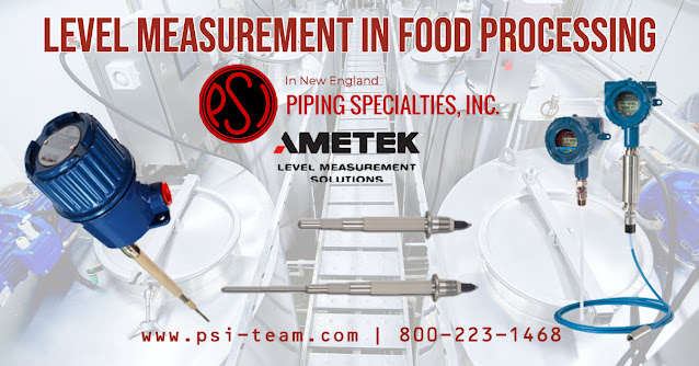
Level Measurement in the Food Processing Industry
Level sensors and controls are crucial in industrial food processing and production facilities to ensure quality and consistency. These devices monitor and regulate the level of liquids, solids, or granular materials in containers, vessels, or silos. Here are some of the most common types of level sensors and controls used in the industry:
- Capacitive level sensors: These sensors detect changes in capacitance caused by the presence or absence of material (liquid or solid) in a container. They measure liquids, powders, or granular materials levels in various applications, including food and beverages.
- Ultrasonic level sensors: Ultrasonic sensors use sound waves to measure the distance between the sensor and the material's surface. These sensors are non-contact and used for measuring levels of liquids or solids in tanks or silos and provide the food industry with accuracy and reliability.
- Radar level sensors: Similar to ultrasonic sensors, radar level sensors use radio waves to measure the distance between the sensor and the material's surface. They are also non-contact and suitable for liquid and solid materials. Radar sensors are particularly useful in challenging environments with dust, vapor, or foam, making them ideal for food processing applications.
- Hydrostatic pressure level sensors: These sensors measure the pressure exerted by the liquid column on the sensor at a specific depth. The pressure re-calibrates to a level measurement. They are primarily used for measuring liquid levels in tanks and have broad use in the food and beverage industry.
- Float level sensors: Float sensors use a floating device to detect the liquid level in a container. The float's vertical or tilting movement triggers a mechanical or electrical signal indicating the liquid level. Food processing plants often use them for simple and cost-effective level measurements.
- Vibrating or tuning fork level sensors: These sensors use a vibrating probe or tuning fork that changes its vibration frequency when it comes into contact with a material. They can detect the presence or absence of material and provide point-level detection of liquids, powders, or granular materials.
- Optical level sensors: Optical sensors use infrared or visible light to detect the presence or absence of a material at a specific level. They are suitable for various materials, including liquids, powders, and solids, in food processing applications where minimum contact with the material is essential.
The choice of level sensor and control system depends on factors like the process material, the required accuracy, the process conditions, and the specific application within the food processing facility. Each technology has advantages and limitations, so careful consideration is needed to select the most suitable option for each application.
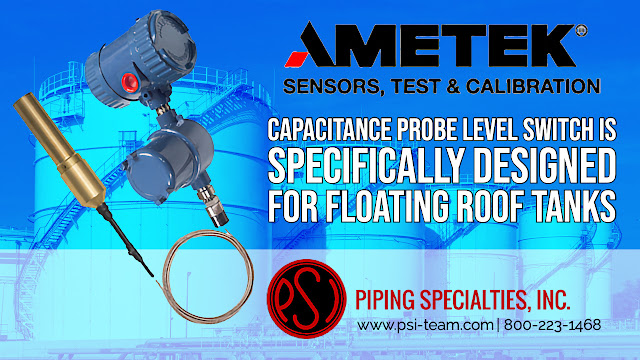
SIL Level Switch Is Specifically Designed for Floating Roof Tanks
- Loop or Line Powered
- Wetted Parts: 316SS 3/4" NPT Mounting, 3/16" FEP insulated flexible and adjustable cable, non-sparking brass sensor.
- Automatic and local or remote manual test functions ensure proper system operation.
- One system fits most floating roof tank applications, reducing field spans
- Adjustable insertion lengths up to 15' (4,6m)
- Excellent trip point accuracy over a wide range of medias and tank roof
Industrial Thermowell Process Connection Types
Water Cut Meters from Drexelbrook
Water cut meters measure the water cut (or BS&W) of oil flowing from a well, a separator, crude oil transfer in pipelines, and tanker loading.
Food Industry Batch Level Control
- 3A designed sanitary sensing elements
- No moving parts
- 3 control points on one vertical sensing element
- Cote-Shield circuitry eliminates false alarms due to coatings
- Designed to endure Clean In Place (CIP) demands
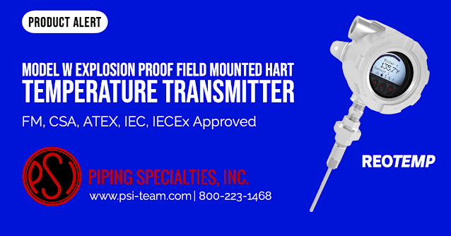
The REOTEMP Model W Explosion Proof, Field Mounted, HART Temperature Transmitter
Submersible Level Transmitters
The Drexelbrook DR3500 80 GHz FMCW Radar for Liquids With Hygienic Requirements
Key DR3500 Features
- Process conditions up to +300⁰F (150⁰C) and 362 psig (25 barg)
- Extensive choice of hygienic process connections
- Small dead zone and beam angle for small and narrow tanks
- Flush-mounted PEEK Lens antenna: CIP/SIP suitable
- 3 Year Warranty
NON-CONTACT LEVEL MEASUREMENT
- Pharmaceutical
- Biotech
- Biopharma
- Food & Beverage
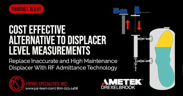
Replace Inaccurate and High Maintenance Displacer Level Controls With RF Admittance Technology
Cost Effective Alternative to Displacer Level Measurements
THE PROBLEM
- Displacer accuracy is dependent on the specific gravity of a fluid. Varying specific gravities and “off spec” product result in significant measurement errors.
- Coating build-up on the displacer body produces errors.
- “Blowdowns” to clean displacer internals and cages is time consuming and expensive.
- Rebuilds due to component wear add significantly to the total cost of ownership.
- Interface measurements are more sensitive to slight specific gravity variances and result in separator throughput lower than the design specification.
THE SOLUTION
- AMETEK Drexelbrook Radio Frequency (RF) Admittance technology eliminates all of the inherent problems with Displacer technology level measurement.
- RF is immune to changes in specific gravity, density, temperature, and pressure.
- Accuracies to 1⁄4 inch of level in short span installations.
- No moving parts to wear, No periodic maintenance.
- Replacement cost differentials covered by eliminating one rebuild.
Piping Specialties / PSI Controls
https://psi-team.com
800-223-1468
The AMETEK Drexelbrook Impulse Guided Wave Radar Level Transmitter
The Drexelbrook Impulse is a guided wave radar (TDR) that measures all liquids and slurries' overall level and other volumetric measures. When competitive water sensors fail, the Impulse continues to provide accurate values.
The Drexelbrook Impulse is a two-wire guided wave radar that uses field-proven TDR level (Time Domain Reflectometry) technology to produce accurate Total Level, Distance, and Volumetric outputs on all liquids and slurries.
The Impulse handles even the most challenging level measuring applications. It will continue to give dependable and accurate measurements even in the presence of disturbances such as agitated or uneven surfaces, foam, or probe coating. Changes in the density and dielectric characteristics, dusts, mist, and turbulence do not affect it. When other water level sensors fail, the Impulse continues to measure.
This water level sensor is a perfect replacement for costly mechanical dispenser systems, with a wide range of probe types and material possibilities for various applications.
This guided wave radar is simple to use for any user due to its simple navigation, push-button setups, and HART connections. It only takes a few minutes to install. Choose your level measuring type and language, and the Impulse is ready to use.
The Impulse guided wave radar is intrinsically safe, explosion-proof, and non-incendive, and it does not require calibration or level changes.
Additionally, Drexelbrook recently introduced an enlarged coaxial sensor for The Impulse GWR. The new 1.66" (42mm) diameter probe provides reliable accuracy within high viscosity liquids. The new enlarged coaxial sensor option for The Impulse GWR allows the material to flow off the sensor easily when used with viscous fluids.
Piping Specialties / PSI Controls
https://psi-team.com
800-223-1468
Drexelbrook CheckWell™ Water Well Level Sensor
The Drexelbrook CheckWell™ water well level sensor automatically monitors the level or drawdown in water wells up to 3000 feet deep.
The AMETEK Drexelbrook CheckWell™ water well level sensor automatically monitors the level or drawdown in water wells up to 3000 feet (914m) deep. It generates a continuous linear output signal that is directly proportional to the well level. This output can be used for remote monitoring/recording, warning signals, and pump control via optional current-actuated relays.
The advantages include quick installation, no manual maintenance, and an all-electronic design for exceptional reliability. Density variations, mineral or oil deposits on the sensing feature, and oil on top of the water do not affect the device.
Level Measurement Solutions for Water Treatment
Several functional level measurement technologies have viable solutions for a broad range of industrial and municipal water treatment applications. Because of the variety of applications that exist and the varying application conditions, no one technology is best suited in all cases.
POINT LEVEL VERSUS CONTINUOUS LEVEL INSTRUMENTS
Regardless of the application, there are two significant classifications of level measurement instrumentation: point level and continuous level measurement.
Point Level (On/Off) measurement indicates the absence or presence of level at a certain threshold (point) within a vessel. Point-level switches perform as high level and spill prevention alarms, low level, pump protection alarms and pump control.
Continuous Level (Proportional) measurement indicates the level in a vessel over the full span of capacity. These devices perform as process control as well as inventory control and management.
LEVEL CONTROL TECHNOLOGY CHOICES
The technologies used to measure level are affected differently by the varying process conditions. Below is a brief description of the different technologies commonly used in a water treatment facility.
RF ADMITTANCE/CAPACITANCE
RF Admittance/Capacitance employs a radio frequency signal and monitors for a change in capacitance. Either the presence or absence of material or how much material is in contact with the sensor, making it highly versatile and a right choice for a wide range of conditions and materials for point or continuous level measurement.
RADAR
Radar utilizes either Pulsed Wave or Frequency Modulated Continuous Wave (FMCW) through-air transmission that allows for an accurate non-contact reading of reflected electromagnetic signals.
MAGNETOSTRICTIVE
Magnetostrictive uses an electric pulse from ferromagnetic wire to accurately detect a float's position with embedded magnets. As the pulse intersects the float's magnetic field, a second pulse reflects an electric circuit that accurately determines the distance and thus the level position.
CONDUCTIVITY SWITCHES
Conductivity switches measure the drop-in resistance when a conductive liquid contacts with two probes or a probe and a vessel wall.
ULTRASONIC (POINT LEVEL)
Ultrasonic (Point Level) measurement electronically resonates a crystal at a fixed frequency to generate sound waves that travel across an air gap to a second crystal. As liquid fills the gap between the two crystals, the second crystal begins to resonate with the first.
ULTRASONIC (CONTINUOUS LEVEL)
Ultrasonic (Continuous Level) measurement uses a transmitter to generate an ultrasonic pulse and measures the time it takes for a reflected signal to return to the transducer to determine a liquid level.
GUIDED WAVE RADAR (GWR)
Guided Wave Radar (GWR) utilizes a Time Domain Reflectometry (TDR) technique by sending a highly focused electronic signal down a metallic rod or flexible cable waveguide. When the transmitted signal intersects the liquid's surface, it reflects along the rod or cable to determine the distance traveled. The level position is then easily inferred.
HYDROSTATIC
Hydrostatic measurement immerses a pressure transmitter with a sensing diaphragm and a sealed electronic circuitry that transmits an analog signal proportional to the liquid level above the sensor.
FLOAT SWITCHES
Float switches rely on a low-density float mounted in a vessel that magnetically couples to a limit switch. A change in fluid height actuates a switch by moving the float.
VIBRATION/TUNING FORK
The Vibration/Tuning fork is piezoelectrically energized and vibrates at a frequency of approximately 1200Hz, and as the process media cover the fork, the frequency shifts. The internal oscillator the frequency shift by and converts it into a switching command.
POINT LEVEL SOLUTIONS
Advanced RF Admittance/Capacitance point level devices are the most versatile of the point level technologies, especially with process media that can coat the sensor. They provide excellent spill/overfill protection. They are simple to install and have no moving parts, making them virtually maintenance-free. Their robust design and circuitry make them an ideal solution for many water treatment applications.
Both tuning forks and ultrasonic gap switches provide reliable high- or low-level measurements in various applications. For non-coating conductive liquids, conductivity switches provide economic priced measurement while float switches appear in many basic applications at very cost-effective prices.
CONTINUOUS LEVEL SOLUTIONS
Mechanical systems such as floats and bubblers require extensive maintenance and are less reliable and accurate than electronic systems. Hydrostatic systems afford better reliability and are simple to use, and can transmit data to another receiver for remote monitoring, recording, and control.
RF Admittance/Capacitance level is a time-proven and one of the best available technologies for indication and control. RF technology inherently provides the highest accuracy and repeatability in interface measurements. Variations in the makeup of upper and lower phases of a liquid have no appreciable effect on system accuracy. Recalibration is not required.
For short-span measurements, RF Admittance technology provides one of the most preferred readings. As the level of measurement span decreases, the more appropriate RF technology becomes. In spans of only a few inches, RF systems can repeatedly produce accuracies of 1/32ths of an inch. RF has the added benefit of not being limited by “dead zones” inherent with many popular technologies often selected for measurement ranges larger than 5 feet.
Non-metallic tanks pose no technical problems for Ultrasonic, Magnetostrictive, Hydrostatic Pressure, Radar, and GWR (Guided Wave Radar) technologies. The GWR approach is suitable for vessels with internal obstructions and uses lower energy levels than airborne radar technologies. Non-contact technologies, such as Radar and Ultrasonic, can have measurement ranges up to 130 feet.
For long-range measurements or headroom limitations, flexible sensors offer insertion lengths up to several hundred feet for Hydrostatic Pressure and RF Admittance technology products. Loop-powered GWR (TDR)-based products allow measurement ranges up to 115 feet in selected applications. Magnetostrictive technology provides an accuracy of 0.1% of measurement span in flexible sensor designs up to a maximum range of 70 feet.
Level Measurement for Water in Sewage Pools
This application takes place at a large power plant well known for its "Green Approach" and it's commitment to ensuring a clean and healthy atmosphere in and around the plant.
The branched sewer system of the power plant requires instant maintenance and control. The plant uses water to operate the turbine. This water and other wastes move to the city’s wastewater treatment plant through the sewage system.
Some of the sewers are dispersed in remote locations around the plant, making it difficult for personal maintenance personnel to approach and repair damage on time. Plant technicians were looking for a solution to control the sewers better and avoid cases where wastewater might overflow.
The sewage pool readings had to be transmitted to the central DCS because the sewage system connects to a central control room. The plant needed a 24/7 watch and an on-site guard to gain maximum control over those sewers.
Technicians also stressed that wastewater flooding was inevitable because it takes time for the equipment to handle blockages. This flooding has caused severe damage to the environment. It was essential to control the wastewater level in the sewers to avoid cases such as these from reappearing.
The Drexelbrook Usonic - The Solution
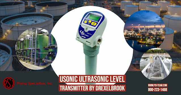
After a lengthy examination of several possibilities, the plant decided to install two Drexelbrook USonic systems in its sewage pools. The ability of USonic to produce non-contact, continuous, and accurate readings of the water level in the pools gave the engineers of the plant a clear picture of the pools' status.
Its compact size and integral construction simplify its installation, offering an efficient solution in no time at all. The USonic had no problem providing 12ft water level readings with a measurement range of up to 30 ft. It can map obstacles in the pool and memorize interfering signals with its scan distance function.
The USonic was linked to the central control system via 4-20mA, allowing the plant engineers to control the water level in the sewers constantly. The engineers know that the sewers would maintain the correct water level, and the system would be alerted in an emergency.
Summary
The two USonic systems installed in the power plant give complete control over the sewers' water level to the plant's engineers. The systems' ability to display continuous level readings around the clock improved maintenance crews handle the sewage system.
To detect sudden blockages and avoid environmental damage on time, they can now save time. The plant received an immediate return on investment due to its compact size and reduced price.
Cost-effective, Non-contact Ultrasonic Level Measurement from Drexelbrook
Affordable, 2-Wire Level Transmitter with the performance and features of premium, line-powered systems.
DOWNLOAD THE USONIC DATA SHEET HERE
USonics ultrasonic technology level products from the Drexelbrook family offers a cost-effective two-wire and line powered versions for the non-contact measurement of liquids and slurries for level, distance, volume, and open channel flow. Level, size, volume, and open-channel flow measurements are easily configured via a menu-driven display. The USonic level transmitter has a 4-20 mA two-wire HART output signal and is suitable for all Class I Div. 1, Zone, I.S., or explosion-proof locations.
For more information contact PSI Controls / Piping Specialties by calling 800-223-1468 or visit https://psi-team.com.Radar Level Measurement: Comparison of 24 GHz and 80 GHz
Radar level transmitters are among the most accurate technology choices for process level and storage tank applications for continuous level measurement under demanding conditions. These transmitters utilize Frequency Modulated Continuous Wave (FMCW) technology that offers superior signal processing capabilities and more reliable measurement than other techniques. The state-of-the-art signal processing capabilities of these transmitters, along with their frequency range, helps to ensure optimum application coverage.
24 GHz radar transmitters cover a broad range of applications, including liquids & solids.
80 GHz radar transmitters are especially beneficial for level measurements in narrow tanks with internal obstructions due to their small beam angle.
This video, courtesy of AMETEK Drexelbrook, demonstrates many of the other differences between 24 GHz and 80 GHz models of radar level transmitters.
For more information on radar level transmitters in New England, contact PSI Controls (Piping Specialties, Inc.). Call them at 800-223-1468 or visit their website at https://psi-team.com.


