Showing posts with label Industrial Valves. Show all posts

Pressure Drop Characteristics Across Different Industrial Valve Types

Pressure Drop Characteristics Across Different Industrial Valve Types

Pressure drop significantly affects the design and operation of industrial valve systems. It refers to the reduction in pressure as fluid flows through a valve. Several factors influence this phenomenon, including valve type, flow rate, fluid properties, and valve geometry. Understanding pressure drop ensures efficient and safe operation of fluid systems. Here’s a detailed description of the pressure drop as it applies to various types of industrial valves:

Ball Valves


Ball valves offer simplicity, durability, and tight seals in industrial applications. The valve uses a spherical ball with a hole through the middle, aligning with the pipeline to allow or block flow.

Pressure Drop Characteristics:
  • Low Pressure Drop: Fully open ball valves exhibit a low pressure drop due to their straight and unobstructed flow path. The smooth, rounded interior of the ball minimizes turbulence and resistance.
  • Impact of Partial Opening: Partially open ball valves significantly increase pressure drop. The fluid navigates around the partially obstructed path, creating turbulence and resistance.
  • Valve Size and Flow Rate: Larger ball valves and higher flow rates reduce the relative pressure drop, but designers must consider potential cavitation and erosion.

Gate Valves


Gate valves primarily control on/off flow in a pipeline. They consist of a gate (or wedge) that moves up and down to start or stop the flow.

Pressure Drop Characteristics:
  • Minimal Pressure Drop when Fully Open: Fully open gate valves exhibit very low pressure drops because the gate remains entirely out of the flow path, allowing fluid to pass with minimal resistance.
  • High Pressure Drop during Partial Operation: Partially open gate valves significantly increase turbulence and pressure drop, making them unsuitable for throttling applications.
  • Design and Maintenance: When open, a straight-through flow path minimizes pressure drop, but over time, wear and tear on the gate and seat can impact performance and increase pressure drop.

Globe Valves


Globe valves excel at regulating flow and are used in applications requiring precise flow control. They consist of a movable disk-type element and a stationary ring seat in a spherical body.

Pressure Drop Characteristics:
  • Higher Pressure Drop: Globe valves inherently exhibit higher pressure drops than ball and gate valves due to the fluid changing direction as it passes through the valve. The tortuous path creates more resistance.
  • Flow Control: Globe valve design makes them ideal for throttling and precise flow control, but this advantage comes with higher pressure drops.
  • Valve Position: The valve opening degree significantly affects the pressure drop. Partial opening creates more resistance and higher pressure drops due to increased turbulence.

Butterfly Valves


Butterfly valves control flow using a rotating disc. They are commonly used in applications requiring quick shut-off and suit large-diameter pipes.

Pressure Drop Characteristics:
  • Moderate Pressure Drop: Fully open butterfly valves exhibit moderate pressure drops because the disc remains in the flow path even when rotated to the open position, creating some obstruction and turbulence.
  • Variable Pressure Drop: The pressure drop increases as the valve moves towards the closed position. The partially obstructed disc increases flow resistance and turbulence.
  • Efficiency and Application: Butterfly valves efficiently handle large volumes of flow with moderate pressure drops. They are often used in water distribution, HVAC systems, and various industrial applications where space and weight considerations matter.

Factors Influencing Pressure Drop Across Valves


Several factors influence pressure drop across industrial valves:
    1. Valve Design: Internal valve geometry, including the flow path and obstructions, plays a significant role.
    2. Flow Rate: Higher flow rates generally increase pressure drop due to greater frictional forces.
    3. Fluid Properties: Fluid viscosity and density affect how they interact with valve surfaces.
    4. Valve Size: Larger valves typically exhibit lower pressure drops for a given flow rate than smaller valves.
    5. Operational Conditions: Valve position (fully open, partially open, or closed) significantly affects pressure drop.

Understanding these characteristics helps select the appropriate valve for specific applications, ensuring efficient and safe operation while maintaining desired flow control and minimizing energy losses.

Piping Specialties / PSI Controls
https://psi-team.com
800-223-1468

What is an External Spring, Lever & Weight Single Disc Check Valve

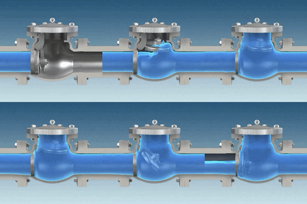
Check valve animation
Single disk check valve animation.
According to Wikipedia, "Check valves are used in many fluid systems such as those in chemical and power plants, and in many other industrial processes."

Check valve symbol
Check valve symbol
As shown in the animation to the left, the single disc (swing) check valve use the directional flow to push open a swinging disk. As long as flow continues, the disk stays raised. But as flow stops, gravity allows the disk to re-seat itself and any reverse flow is prevented by the closed disk. As reverse flow pressure increases, the swing check valves seating increases as well.

Single disc check valves also use springs, levers and/or weights mounted on the valve to allow for better control of surge and to prevent the valve from slamming closed. These assemblies are used to vary the valve’s closing operation in order to reduce the severity of the closing water hammer.

spring, level and weight assisted check valve
External spring, external spring & lever, and external spring, level & weight designs (left to right).
Courtesy of Champion Valve.
For more information on any industrial check valve, contact Piping Specialties, Inc. by visiting https://psi-team.com or calling 800-223-1468.

What Are Industrial Ball Valves?

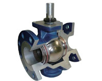
Internal view of a ball valve
(MOGAS)
Ball valves are defined by their body style, the five major styles being: Uni-body; 3-piece; split-body; top-entry; and welded body. They are further defined by the machined hole in their ball (also known as the port); the categories being "standard port" or "full port".

On a full port valve, the port is the same size as the pipeline, resulting in a better flow profile and no restriction or pressure drop. A full ported ball valve, with better flow coefficients, comes at a higher price. In many application they are necessary because a reduction in diameter, or the resulting change in flow, can be detrimental.

The reduction in a standard port valve is one pipe size smaller than the pipe connected to the valve, resulting in restricted flow and increased velocity through the valve.

2-piece and unibody ball valves
2-piece and unibody ball valves (Flo-Tite)
Standard port and full port valves are not usually recommended for throttling service due the a very
non-linear flow characteristic. Characterizing the port with a special shaped orifice can improve the valve linearity and provide good control. V-port ball valves incorporate a machined "V" in the seat around the outlet side of the valve. The "V" provides a more controllable flow pattern and is desirable when ball valves are used as control valves.

A cavity filled ball valve is used in applications where cleanliness or sanitary conditions exist. Any voids, gaps or spaces between the ball, seat and stem that allow bacteria or contaminates to accumulate are filled.  The proper cavity filler material is selected consistent with the process media, application and level of cleanliness required. Cavity fillers eliminate the spaces and voids where contaminants accumulate and provides easy "flushing" (cleaning) of the valve.

In a trunnion mounted ball valve, the valve stem is mechanically attached to the ball. Trunnion mounted valves are mostly used in applications on large diameter gas and oil pipelines and at high pressures.

Most ball valves however, are designed with a “floating ball” and not held mechanically in place by a trunnion. This allows the ball to be "pushed" slightly downstream and seal itself better against the seat. One advantage to this design is that a valve using a floating ball, and fitted with metal seats, can be used for "fire-safe" applications. This means that if the valve is subject to high temperatures, such as those presented in a fire, the "soft" part of the seat will melt away, and allow the ball to secure itself against the metal seat, and thus not allow material to pass and potentially feed the fire.

For best service life and optimum safety, please review your application with a qualified ball valve applications consultant prior to specifying an industrial ball valve.

Industrial Valve Basics

Industrial Valves
Industrial multi-port ball valves (Flo-Tite)
Valves are mechanical devices, essential control and regulating components of a piping system. They are the controlling element within any fluid handling systems; they control the flow and/or pressure of fluids such as liquids, gases, vapors, slurries, and more.

Because of the variety of fluids valves can accommodate, care and consideration are needed when selecting a valve that provides the right service level at the right price point.

For this reason, the types, models, and classifications of valves vary, however, they all offer the same basic function:

  • Stopping and starting flow
  • Increasing or reducing flow
  • Controlling the direction of flow
  • Regulating a flow or process pressure

To begin, the first classification of valves are the valves themselves; there are seven common types: gate, globe, plug, ball, butterfly, check, and diaphragm. Each of these valves has models, the second classification. Depending on the valve of choice, the valves can be self-operated, manually operated, or controlled with an actuator that is pneumatic, electric, or hydraulic.

The third classification is based on mechanical motion of the valve closure.

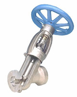
Linear industrial valve
Internal view of
linear industrial valve
(Conval)
Linear Valve: the valve closure moves in a straight line between open and closed positions,
providing fully closed, a range of partially open, and fully open positions. Partially open positions provide throttling of the fluid flow at levels between no flow and full flow. Gate, globe, and diaphragm valves are characterized by linear motion. These valves are also referred to as multi-turn valves, because of the mechanical drive arrangement that some utilize to move the valve closure.

Internal view of rotary valve
Internal view of rotary (ball) valve.
Courtesy of Flo-Tite.
Rotary Valve: the valve closure travels along a circular or angular path; e.g. butterfly, plug, and ball valves. Rotary valves generally require an approximate quarter turn to complete the motion between fully open and fully closed positions.

There are many product and performance attributes to consider in the valve selection process, low maintenance burden and cost usually being highly ranked. It is also important to match the valve construction to the fluid the valve will be handling, e.g. is it corrosive or erosive? The level of physical stress, including frequency of use, temperature, pressure, and the speed at which flow is to be interrupted may be of concern.

Ultimately, each industrial process application will benefit from a carefully selected valve that closely matches the process performance requirements. Share your fluid control requirements and challenges with an industrial valve expert, combining your own process knowledge and experience with their product application expertise to develop effective solutions.