Understanding Hydrostatic Pressure

Hydrostatic level transmitter
(Drexelbrook)
Pressure measurement is an inferential way to determine the height of a column of liquid in a vessel in process control. The vertical height of the fluid is directly proportional to the pressure at the bottom of the column, meaning the amount of pressure at the bottom of the column, due to gravity, relies on a constant to indicate a measurement. Regardless of whether the vessel is shaped like a funnel, a tube, a rectangle, or a concave polygon, the relationship between the height of the column and the accumulated fluid pressure is constant. Weight density depends on the liquid being measured, but the same method is used to determine the pressure.

A common method for measuring hydrostatic pressure is a simple gauge. The gauge is installed at the bottom of a vessel containing a column of liquid and returns a measurement in force per unit area units, such as PSI. Gauges can also be calibrated to return measurement in units representing the height of liquid since the linear relationship between the liquid height and the pressure. The particular density of a liquid allows for a calculation of specific gravity, which expresses how dense the liquid is when compared to water. Calculating the level or depth of a column of milk in a food and beverage industry storage vessel requires the hydrostatic pressure and the density of the milk. With these values, along with some constants, the depth of the liquid can be calculated.

The liquid depth measurement can be combined with known dimensions of the holding vessel to calculate the volume of liquid in the container. One measurement is made and combined with a host of constants to determine liquid volume. The density of the liquid must be constant in order for this method to be effective. Density variation would render the hydrostatic pressure measurement unreliable, so the method is best applied to operations where the liquid density is known and constant.

Interestingly, changes in liquid density will have no effect on measurement of liquid mass as opposed to volume as long as the area of the vessel being used to store the liquid remains constant. If a liquid inside a vessel that’s partially full were to experience a temperature increase, resulting in an expansion of volume with correspondingly lower density, the transmitter will be able to still calculate the exact mass of the liquid since the increase in the physical amount of liquid is proportional to a decrease in the liquid’s density. The intersecting relationships between the process variables in hydrostatic pressure measurement demonstrate both the flexibility of process instrumentation and how consistently reliable measurements depend on a number of process related factors.

Visit PSI-Team.com for more information on pressure and level instrumentation.

Industrial Valve Basics

Industrial Valves
Industrial multi-port ball valves (Flo-Tite)
Valves are mechanical devices, essential control and regulating components of a piping system. They are the controlling element within any fluid handling systems; they control the flow and/or pressure of fluids such as liquids, gases, vapors, slurries, and more.

Because of the variety of fluids valves can accommodate, care and consideration are needed when selecting a valve that provides the right service level at the right price point.

For this reason, the types, models, and classifications of valves vary, however, they all offer the same basic function:

  • Stopping and starting flow
  • Increasing or reducing flow
  • Controlling the direction of flow
  • Regulating a flow or process pressure

To begin, the first classification of valves are the valves themselves; there are seven common types: gate, globe, plug, ball, butterfly, check, and diaphragm. Each of these valves has models, the second classification. Depending on the valve of choice, the valves can be self-operated, manually operated, or controlled with an actuator that is pneumatic, electric, or hydraulic.

The third classification is based on mechanical motion of the valve closure.

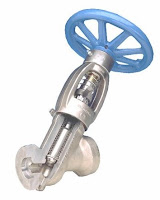
Linear industrial valve
Internal view of
linear industrial valve
(Conval)
Linear Valve: the valve closure moves in a straight line between open and closed positions,
providing fully closed, a range of partially open, and fully open positions. Partially open positions provide throttling of the fluid flow at levels between no flow and full flow. Gate, globe, and diaphragm valves are characterized by linear motion. These valves are also referred to as multi-turn valves, because of the mechanical drive arrangement that some utilize to move the valve closure.

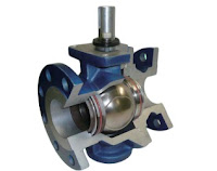
Internal view of rotary valve
Internal view of rotary (ball) valve.
Courtesy of Flo-Tite.
Rotary Valve: the valve closure travels along a circular or angular path; e.g. butterfly, plug, and ball valves. Rotary valves generally require an approximate quarter turn to complete the motion between fully open and fully closed positions.

There are many product and performance attributes to consider in the valve selection process, low maintenance burden and cost usually being highly ranked. It is also important to match the valve construction to the fluid the valve will be handling, e.g. is it corrosive or erosive? The level of physical stress, including frequency of use, temperature, pressure, and the speed at which flow is to be interrupted may be of concern.

Ultimately, each industrial process application will benefit from a carefully selected valve that closely matches the process performance requirements. Share your fluid control requirements and challenges with an industrial valve expert, combining your own process knowledge and experience with their product application expertise to develop effective solutions.

Assembling the Pratt Industrial BF Series Resilient Seated Butterfly Valve

Pratt Industrial BF Series butterfly valve
Pratt BF Series
The Pratt Industrial BF Series butterfly valve is recognized for it's quality and durability for use in these industries: Mining, Food/Beverage, Power, OEM’s, Chemical/Pharmaceutical, Desalination, Petroleum/Oilfield, Ultra Pure Water, Transportation, Marine, Irrigation, and HVAC.

The specifications are:
  • Sizes: 2" through 48"
  • Body: Ductile Iron (65-45-12)
  • Disc: Ductile Iron Nickle Plated, Ductile Iron Nylon 11, CF8M Stainless Steel, Aluminum Bronze
  • Stem: 416 S.S. Heat Treated
  • Resilient Seat: EPDM, Buna-N, Viton
  • Actuation Options: Worm Gear, Lever, Pneumatic, Electric
  • Pressure Ratings: 2" – 12" 230psi; 14" – 48" 150psi
Features:
  • Innovative 3 point connection, tongue andgroove seat allows for higher pressure rating and full Vacuum service
  • Unique secondary shaft seals prevent leakage from shaft.
  • Two piece shaft design provides maximum strength and a high flow characteristic disc.
Watch video below for assembly instructions:


For more information about the valve, read the BF Series brochure below. The full Pratt BF Series brochure PDF can be downloaded here.

An Introduction to Industrial Flowmeters

Electromagnetic flowmeter
(courtesy of Azbil)
Flowmeters measure the rate or quantity of moving fluids, in most cases liquid or gas, in an open channel or closed conduit. There are two basic flow measuring systems: those which produce volumetric flow measurements and those delivering a weight or mass based measurement. These two systems, required in many industries such as power, chemical, and water, can be integrated into existing or new installations. For successful integration, the flow measurement systems can be installed in one of several methods, depending upon the technology employed by the instrument. For inline installation, fittings that create upstream and downstream connections that allow for flowmeter installation as an integral part of the piping system. Another configuration, direct insertion, will have a probe or assembly that extends into the piping cross section. There are also non-contact instruments that clamp on the exterior surface of the piping and gather measurements through the pipe wall without any contact with the flowing media.

Because they are needed for a variety of uses and industries,
Orifice plate
Orifice plate
(Flow-Lin)
there are multiple types of flowmeters classified generally into four main groups: mechanical, inferential, electrical, and other.

Quantity meters, more commonly known as positive displacement meters, mass flowmeters, and fixed restriction variable head type flowmeters all fall beneath the mechanical category. Fixed restriction variable head type flowmeters use different sensors and tubes, such as orifice plates, flow nozzles, and venturi and pitot tubes.

Inferential flowmeters include turbine and target flowmeters, as well as variable area flowmeters also known as rotameters.

Thermal Mass Flowmeter
(Kurz)
Laser doppler anemometers, ultrasonic flowmeters, thermal mass, and electromagnetic flowmeters are all electrical-type flowmeters.

The many application classes throughout the processing industries have led to the development of a wide range of flow measurement technologies and products. Each has its own advantages under certain operating conditions. Sorting through the choices and selecting the best technology for an application can be accomplished by consulting with a process instrumentation specialist. The combination of your own process knowledge and experience with their product application expertise will develop an effective solution.

For more information regarding any type or style of flowmeter, visit http://www.psi-team.com or call 800-223-1468.

PSI Controls and Piping Specialties Intro Video

For those who may not know us, please take a minute to watch our 1 minute intro video.

Level Measurement Technologies Provide Accurate Level Control & Ignore Foams in Filler Bowl Applications

Filler Bowl Applications
RF Admittance and Magnetostrictive technologies have a proven performance record in gravity feed flow control for the dispensing of liquids into bottles or containers.

In high speed bottling operations many different filling methods can be used depending on the nature of the product and type of container being filled. For many Food and Beverage, and Pharmaceutical applications the preferred filling method is by using level measurements to control the gravity ow of liquids into bottles or containers from the filler bowl. The level measurement method is very consistent with liquids and slurries to prevent over-filling or under-filling of a bottle or container by keeping a consistent product level in the filler bowl. 

Level filling is the oldest filling method and is still largely favored in specific markets. This is largely due to products being sold in translucent containers. The consumer expects to see that all containers are filled to the same precise level and will reject a container with a level lower than others on the shelf. 

Filler Bowl ApplicationsIn a gravity feed filler bowl, the natural head pressure of the liquid is used to ll each bottle. The liquid level in the filler bowl must be kept at a constant level so the pressure within the filler bowl remains constant. This permits each bottle or container to ll to the correct level in the same amount of time. 

The Problem: 

Hydrostatic pressure level measurement systems, which have been traditionally used for this application, are found to have errors in level measurements when changing from one process material to the next, which usually has a slightly different specific gravity. As the process fluid’s specific gravity is changed, this leads to either an over- ll or under- ll condition. 

The Solution: 

AMETEK-Drexelbrook provides sanitary 3A approved systems in both RF Admittance and Magnetostrictive technologies for use in filler bowl measurements that remain unaffected by changes in specific gravity, changes in temperature or changes in pressure or vacuum. Both technologies can provide the accuracies that are required for reliable performance in the face of light or heavy liquid viscosities, foaming conditions, and have the ability to ignore process coatings that may develop on the sanitary sensors. The sensors are of rugged construction and will not be affected by the shock or vibration of the bottling process. 

RF Admittance systems are supplied with a Triclover fitting with a rigid Teflon coated sensor the length of the measurement range. Accuracy is ±1% of measured span. Systems are agency approved as intrinsically safe for Class I, Div. 1 hazardous installations. RF Admittance has the ability to measure a wide range of process materials and ignore most foam and process build-up on the sensor. Systems are powered by a two-wire, 24Vdc power source. 

Magnetostrictive systems are supplied with a Triclover fitting and use a 240 grit finished 316SS rigid sensor and oat. Accuracy is 0.1% of measured span. Systems are agency approved as intrinsically safe for Class I, Div. 1 hazardous installations. Magnetostrictive systems can easily ignore foaming conditions as the oat will sink through the foam and rest on the liquid surface. Systems are powered by a two-wire, 24Vdc power source. 

AMETEK-Drexelbrook systems can provide analog 4-20 mA, HART, or Honeywell DE outputs. Sensor lengths can be as small as a few inches to over 10 ft. All systems are maintenance free and can be easily con gured without complex calibration. 

AMETEK-Drexelbrook has successfully supplied filler bowl level measurement systems to many major Food & Beverage and Pharmaceutical customers over the past 40 years and have hundreds of successful applications on products such as milk, fruit and vegetable juices, jellies, baby foods, soups, beer, spirits, ground meat, pet foods, sodas, and more. 

Welcome to the PSI Controls and Piping Specialties Blog

We hope you find our product and application articles helpful and informative. Our goal is to do our part in improving access to process control information and knowledge through Internet resources. Please feel free to reach out and contact us if you ever have a question or comment.

Sincerely,
PSI Team