Showing posts with label actuator. Show all posts

Understanding Rack & Pinion Pneumatic Valve Actuators

Internal view of rack and pinion actuator.
Internal view of rack and pinion actuator (UniTorq)
Rack & Pinion actuators are designed for operating quarter-turn valves such as butterfly, plug, and ball valves or for actuating industrial or commercial dampers.

The rotational movement of a rack and pinion actuator is accomplished via linear motion and two gears. A circular gear, referred to a “pinion” engages the teeth of a linear gear “bar” referred to as the “rack”.

In a pneumatic actuator, pistons are attached to the rack. As air or spring power is applied the to piston, the rack is “pushed” inward or “pulled” outward. This dual direction linear movement is transferred to the rotary pinion gear providing bi-directional rotation.

Rack and Pinion Animation
Pneumatic actuators have cylinders with pistons and springs that provide the linear movement. When one side of the piston is pressurized with air, gas or oil, the pinion bearing turns in one direction. When the air, gas or oil from the pressure side is vented, a spring (spring-return actuators) may be used to rotate the pinion gear in the opposite direction. A “double acting” actuator does not use springs, instead using the air, gas or oil supply on the opposing side of the piston to turn the pinion gear in the opposite direction.

Pneumatic pneumatic rack and pinion actuators are compact and save space. They are reliable, durable and provide a good life cycle. Mechanical wear of the heads and seals are their primary disadvantage.

Most actuators are designed for 100-degree travel with clockwise and counterclockwise travel adjustment for open and closed positions. World standard ISO mounting pad are commonly available to provide ease and flexibility in direct valve installation.
Rack and Pinion Actuator
Rack and Pinion Actuator (UniTorq)
NAMUR mounting dimensions on actuator pneumatic port connections and on actuator accessory holes and drive shaft are also common design features to make adding pilot valves and accessories more convenient.

Feel free to contact Piping Specialties, Inc. at www.psi-team.com or 800-223-1468 with any questions you may have about valve actuation.

Industrial Valve Basics

Industrial Valves
Industrial multi-port ball valves (Flo-Tite)
Valves are mechanical devices, essential control and regulating components of a piping system. They are the controlling element within any fluid handling systems; they control the flow and/or pressure of fluids such as liquids, gases, vapors, slurries, and more.

Because of the variety of fluids valves can accommodate, care and consideration are needed when selecting a valve that provides the right service level at the right price point.

For this reason, the types, models, and classifications of valves vary, however, they all offer the same basic function:

  • Stopping and starting flow
  • Increasing or reducing flow
  • Controlling the direction of flow
  • Regulating a flow or process pressure

To begin, the first classification of valves are the valves themselves; there are seven common types: gate, globe, plug, ball, butterfly, check, and diaphragm. Each of these valves has models, the second classification. Depending on the valve of choice, the valves can be self-operated, manually operated, or controlled with an actuator that is pneumatic, electric, or hydraulic.

The third classification is based on mechanical motion of the valve closure.

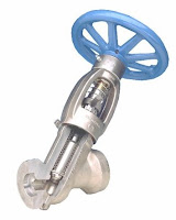
Linear industrial valve
Internal view of
linear industrial valve
(Conval)
Linear Valve: the valve closure moves in a straight line between open and closed positions,
providing fully closed, a range of partially open, and fully open positions. Partially open positions provide throttling of the fluid flow at levels between no flow and full flow. Gate, globe, and diaphragm valves are characterized by linear motion. These valves are also referred to as multi-turn valves, because of the mechanical drive arrangement that some utilize to move the valve closure.

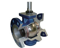
Internal view of rotary valve
Internal view of rotary (ball) valve.
Courtesy of Flo-Tite.
Rotary Valve: the valve closure travels along a circular or angular path; e.g. butterfly, plug, and ball valves. Rotary valves generally require an approximate quarter turn to complete the motion between fully open and fully closed positions.

There are many product and performance attributes to consider in the valve selection process, low maintenance burden and cost usually being highly ranked. It is also important to match the valve construction to the fluid the valve will be handling, e.g. is it corrosive or erosive? The level of physical stress, including frequency of use, temperature, pressure, and the speed at which flow is to be interrupted may be of concern.

Ultimately, each industrial process application will benefit from a carefully selected valve that closely matches the process performance requirements. Share your fluid control requirements and challenges with an industrial valve expert, combining your own process knowledge and experience with their product application expertise to develop effective solutions.