Jet Pump (Eductor) Theory of Operation

Jet Pump (Eductor)
Jet Pump (courtesy of Emerson Penberthy)
Also known as eductors, jet pumps operate on the principles of fluid dynamics. An operating fluid medium, which is referred to as the MOTIVE, placed under pressure, enters the inlet and is forced through the nozzle where it is converted into a high-velocity stream. This high-velocity stream decreases the pressure in the suction chamber, creating a partial vacuum that draws the suction material into the chamber where it is entrained by the motive medium. Once the SUCTION stream is drawn in, shear between the motive medium and the transported material causes both media to be intermixed and pumped out the DISCHARGE outlet, dispelled at a pressure greater than that of the SUCTION stream but lower than that of the MOTIVE. This basic principle of fluid dynamics is what makes jet pumps work.

MOTIVE:

This function is the power phase of the pumping operation. At this stage, the velocity of the motive medium increases as it passes through a nozzle. This phase of the pumping operation takes advantage of the kinetic properties of the motive medium, whether it is liquid, steam or gas. Because of this, design differences may exist within the motive connection of the jet pump.

For instance, jet pumps with liquid motives use a converging nozzle, since liquids usually cannot be compressed. On the other hand, jet pumps with gas or steam motives use converging/ diverging nozzles to achieve transsonic flow velocity. The critical flow paths of all jet pumps are machined smoothly with no abrupt turns or steps in order to produce the most efficient flow during the motive function. Without this direct flow design and smooth interior surface, the jet pump would not operate at peak efficiency.
Jet Pump (Eductor) Theory of Operation
Click for larger view.
This connection is where the pumping action takes place. The high velocity stream of the motive causes a drop in pressure in the suction chamber. This allows pressure in the suction vessel to push a liquid, steam or gas into the suction chamber of the jet pump. This, in turn, is entrained by the high-velocity motive stream emerging from the inlet nozzle.

DISCHARGE:

As the motive flow combines with the suction medium, some kinetic energy of the motive is transferred to the suction, mixing and discharging at a reduced pressure. The amount of pressure that can be recovered depends on the ratio of motive flow to suction flow, plus the amount of suction pressure built up in the suction vessel. Kinetic energy is converted back to pressure as the mixed media passes through the diverging taper and is discharged from the pump.

For more information about jet pumps and their applications, contact Piping Specialties, Inc. by calling 800-223-1468 or by visiting their web site at https://psi-team.com.

Direct Acting and Pilot Operated Pressure Relief Valve Operation


relief valve
Here is a clear and well illustrated tutorial video demonstrating the operational principals of pilot and direct acting pressure relief valves.

There are many available configurations of pressure relief and safety valves, each tailored to accommodate a particular set of application criteria. Understanding how these valves work is important to their proper selection and application to industrial processes and their control.

Safety mindedness is critical for these applications, and you should always talk to an experienced applications expert before specifying or installing these products. Product performance and selection information, as well as application assistance, is available from your local product specialists.

Piping Specialties, Inc.
https://psi-team.com
800-223-1468

Problems with Measuring Level of High Density Pulp Stock

Level Measurement in Pulp Stock
Level Measurement in Pulp Stock has posed problems for a wide range of level measurement technologies. In most pulp mills this is the most challenging application on site.

The environment in the high-density pulp tank is very corrosive to most common metals and the clouds of dense steam vapors that rise from the stock and foaming surface of the level are a constant source of signal loss for many non-contact technologies.

Due to the size of the vessel and density of the stock, mechanical devices are typically short  lived.Stock coatings that form on all interior surfaces add additional mechanical stress and the pulp coating deposits can adversely affect accurate level measurement performance.

One of the challenges of a level measurement device is to control the level in the stock tank, thereby helping to control the average pulp density by controlling the speed of the pump.The response time of the level measurement system is critical in controlling the pump speed and reducing pump oscillations and surges that will eventually reduce the life of the pump.Too slow of a response from the level instrument will allow the level to rise above it ’s optimum density level and cause excessive loading and wear on the pump.


Piping Specialties, Inc.
PSI Controls
https://psi-team.com
800-223-1468


Types of Pneumatic Valve Actuators

Scotch-yoke actuators
Scotch-yoke actuators (Morin)
Pneumatic valve actuators all provide the same function:  They convert air pressure to rotational

movement and are designed to open, close, or position a quarter-turn valve.  These include ball valves, plug valves, butterfly valves, or other types of 90 degree rotational valves.

The basic design variations of pneumatic valve actuators are as follows:

  • Rack and pinion
  • Scotch-yoke
  • Rotary vane

Let's review each of these in detail:

Rack and Pinion Actuators

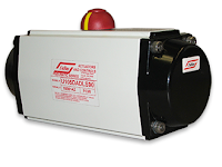
Rack and pinion actuator
Rack and pinion actuator (Unitorq)
These actuators are sometimes referred to as, “lunch box,” because they, well, look like a lunch box. This actuator uses opposing pistons with integral gears to engage a pinion gear shaft to produce rotation. They are usually more compressed than a scotch yoke, have standardized mounting patterns, and produce output torques suitable for small-to-medium sized valves.  Rack and pinion nearly always include standard bolting and coupling patterns to directly attach a valve, solenoid, limit switch or positioner.  One of their features include several smaller coil springs mounted internally, which provide the torque to return the valve to its starting position.

Scotch-yoke Actuators 

Scotch-yoke actuators
Scotch-yoke actuators internal view.
These actuators come in a multitude of sizes, but are usually used on larger valves because they can produce a very high torque output.  They employ a pneumatic piston mechanism to transfer movement to a linear push rod.  That rod, in turn, engages a pivoting lever arm to provide rotation. Spring return units have a large return spring module mounted on the opposite end of the piston mechanism working directly against the pressurized cylinder.

Rotary Vane Actuators 

Rotary vane actuators
Rotary vane actuator animation.
These actuators are usually used when the application requires a significant space savings.  They take up less space when comparing size-to-torque with rack and pinion and scotch yoke. Rotary van actuators also benefit from a reputation of longevity.  They contain fewer moving parts than other types of pneumatic valve actuators.  Rotary vane actuators use externally mounted, helically wound "clock springs" for their spring return mechanism.

These style of valve actuators can all be secured with direct acting or spring return versions. Direct acting actuators use the air supply to move the actuator in both directs (open and close). Spring return actuators, as the name describes, uses springs to move the actuator back to its "resting" state. Converting a version from direct acting to spring return is done through simple modifications, typically just adding an external spring module, or removing the end caps from rack and pinion actuators and installing several coil springs.

When considering the choice of pneumatic valve actuators, your decision comes down to size, power, torque curve and the ease of adding peripherals. To ensure that your valve actuation package will be optimized for safety, longevity, and performance, the advice of a qualified valve automation expert should be sought out. That expert will be able to help you with the best selection of the appropriate valve actuator for any quarter turn valve application.

For more information on valve actuation, contact Piping Specialties, Inc.
https://psi-team.com
800-223-1468

Understanding Differential Flow Measurement


The differential flow meter is the most common device for measuring fluid flow through pipes. Flow rates and pressure differential of fluids, such as gases vapors and liquids, are explored using the orifice plate flow meter in the video below.

The differential flow meter, whether Venturi tube, flow nozzle, or orifice plate style, is an in line instrument that is installed between two pipe flanges.

The orifice plate flow meter is comprised the circular metal disc with a specific hole diameter that reduces the fluid flow in the pipe. Pressure taps are added on each side at the orifice plate to measure the pressure differential.

According to the Laws of Conservation of Energy, the fluid entering the pipe must equal the mass leaving the pipe during the same period of time. The velocity of the fluid leaving the orifice is greater than the velocity of the fluid entering the orifice. Applying Bernoulli's Principle, the increased fluid velocity results in a decrease in pressure.

As the fluid flow rate increases through the pipe, back pressure on the incoming side increases due to the restriction of flow created by the orifice plate.

The pressure of the fluid at the downstream side at the orifice plate is less than the incoming side due to the accelerated flow.

With a known differential pressure and velocity of the fluid, the volume metric flow rate can be determined. The flow rate “Q”, of a fluid through an orifice plate increases in proportion to the square root the pressure difference on each side multiplied by the K factor. For example if the differential pressure increases by 14 PSI with the K factor of one, the flow rate is increased by 3.74.

Piping Specialties, Inc. / PSI Controls
800-223-1468
https://psi-team.com

MOGAS Industries Authorized Valve Automation Center


Piping Specialties, Inc. is an authorized Valve Automation Center for MOGAS Industries, Inc. serving New England and the Northeast U.S.A. MOGAS is the leading manufacturer of severe service ball valves for extreme industrial applications.

Piping Specialties, Inc.
https://psi-team.com
800-223-1468

The Azbil AX Series of Vortex Inline Flow Meters

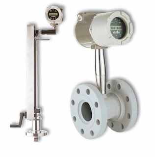
Azbil AX Series
The AX Series of Vortex inline flowmeters measure flows of liquid, gas, and steam by measuring the rate at which vortices are alternately shed from a bluff body; this rate has been shown to be directly proportional to the flow velocity.

As flow passes a bluff body in the stream, vortices create pressure differentials which are measured by a piezoelectric crystal sensor, which converts these pulses into electrical signals. The meter uses an all-welded sensor design to create a strong unit and minimize potential leakage.

The Azbil AX Series can be configured to measure anything from simple volumetric flow of liquids and saturated steam up through multivariable measurements, including mass flow rate, pressure, temperature and density of liquids and steam.

Insertion style vortex meters measure fl ow by detecting the local velocity at a strategically located position within the pipe. Using local velocity, calculated by measuring the rate at which vortices are alternately shed from a bluff body within the sensor, the Azbil AX2300 uses parameters such as fluid type, pipe size, and Reynolds number to calculate accurate measurements.

Download the Azbil AX Series Vortex Flow Meter brochure here.