Understanding Differential Flow Measurement


The differential flow meter is the most common device for measuring fluid flow through pipes. Flow rates and pressure differential of fluids, such as gases vapors and liquids, are explored using the orifice plate flow meter in the video below.

The differential flow meter, whether Venturi tube, flow nozzle, or orifice plate style, is an in line instrument that is installed between two pipe flanges.

The orifice plate flow meter is comprised the circular metal disc with a specific hole diameter that reduces the fluid flow in the pipe. Pressure taps are added on each side at the orifice plate to measure the pressure differential.

According to the Laws of Conservation of Energy, the fluid entering the pipe must equal the mass leaving the pipe during the same period of time. The velocity of the fluid leaving the orifice is greater than the velocity of the fluid entering the orifice. Applying Bernoulli's Principle, the increased fluid velocity results in a decrease in pressure.

As the fluid flow rate increases through the pipe, back pressure on the incoming side increases due to the restriction of flow created by the orifice plate.

The pressure of the fluid at the downstream side at the orifice plate is less than the incoming side due to the accelerated flow.

With a known differential pressure and velocity of the fluid, the volume metric flow rate can be determined. The flow rate “Q”, of a fluid through an orifice plate increases in proportion to the square root the pressure difference on each side multiplied by the K factor. For example if the differential pressure increases by 14 PSI with the K factor of one, the flow rate is increased by 3.74.

Piping Specialties, Inc. / PSI Controls
800-223-1468
https://psi-team.com

MOGAS Industries Authorized Valve Automation Center


Piping Specialties, Inc. is an authorized Valve Automation Center for MOGAS Industries, Inc. serving New England and the Northeast U.S.A. MOGAS is the leading manufacturer of severe service ball valves for extreme industrial applications.

Piping Specialties, Inc.
https://psi-team.com
800-223-1468

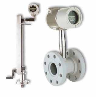
The Azbil AX Series of Vortex Inline Flow Meters

Azbil AX Series
The AX Series of Vortex inline flowmeters measure flows of liquid, gas, and steam by measuring the rate at which vortices are alternately shed from a bluff body; this rate has been shown to be directly proportional to the flow velocity.

As flow passes a bluff body in the stream, vortices create pressure differentials which are measured by a piezoelectric crystal sensor, which converts these pulses into electrical signals. The meter uses an all-welded sensor design to create a strong unit and minimize potential leakage.

The Azbil AX Series can be configured to measure anything from simple volumetric flow of liquids and saturated steam up through multivariable measurements, including mass flow rate, pressure, temperature and density of liquids and steam.

Insertion style vortex meters measure fl ow by detecting the local velocity at a strategically located position within the pipe. Using local velocity, calculated by measuring the rate at which vortices are alternately shed from a bluff body within the sensor, the Azbil AX2300 uses parameters such as fluid type, pipe size, and Reynolds number to calculate accurate measurements.

Download the Azbil AX Series Vortex Flow Meter brochure here.


Using Link-Seal in Combination with Century-Line Sleeves or Cell-Cast Disks for Sealing Pipe Penetrations when Pouring Walls, Floors or Ceilings


Sealing pipes passing through concrete barriers can be one of the really tough challenges confronted by designers and installers of any piping system. But there's a way to simplify the whole process. All it takes is the system approach.  Link-Seal in combination with Century Line sleeves makes for a dynamic combination.  Just what you need to quickly and easily seal any cylindrical object passing through concrete poured walls, floors, and ceilings.

Link-Seal is a flexible belt of interconnected rubber links used to seal the void area or annular space between a cylindrical pipe and round wall opening. Be it a steel sleeve, plastic sleeve, or poured hole, installation is easy. The belt is simply wrapped around the pipe connected and secured by tightening the bolt heads moving clockwise around the seal. Pressure plates on each side of the link applied the compression necessary to expand the rubber. As the bolts are tightened, the links enlarge from a free to an expanded state, transforming the belt of separate links into a hydrostatic seal capable of holding in excess of 20 PSIG with a safety factor of 5 to 1. In the laboratory under controlled conditions, Link-Seal has been successfully tested to 100 PSIG and above.  In addition, accelerated aging tests have shown Link-Seal to be capable of providing maintenance-free service over performance life cycles estimated at 40 years or more.

In the real world, Link-Seal improves overall system reliability by effectively dampening the damaging effects of vibration.  Link-Seals reduce fatigue on pipe welds, flanges and threaded connections. As an added bonus, they may also be used to isolate stray electric current passing through pipes and casings. Applications for Link-Seal are almost infinite. In fact, any cylindrical object may be quickly easily and permanently sealed as they pass through barriers of all kinds.

For more information on Link-Seal, contact:
Piping Specialties, Inc.
https://psi-team.com
800-223-1468

Happy Holidays from Piping Specialties / PSI Controls

From all of us at Piping Specialties/PSI Controls, we wish our customers, partners and vendors a safe and happy holiday season and a wonderful 2019!


What Are Trunnion Mount Ball Valves?

Trunnion ball valve design. Trunnions highlighted.
Ball valves are well understood in process control and industrial piping systems. Their simple 1/4 turn operation, compact form factor, bidirectional sealing, and tight shutoff make them a very popular choice for a wide range of applications.

Although there are many varieties of seat designs, body styles, and flow patterns, ball valves can be separated in to two main groups, distinguished by a primary design element - the mounting method of the valve ball.

The two groups are:
  • Floating ball
  • Trunnion mounted ball
Floating ball valves use the body and valve seats to position and hold the ball in the media flow path, allowing the flow force to lodge the "floating" ball firmly against the downstream seat. In this style, the ball is not mechanically held in place, thus the term "floating". Floating ball valves are, in general, limited to applications with smaller sizes and lower pressure ranges because, at some point, the fluid pressure on the ball may exceed the seat and trim's ability to hold the ball properly in place.

Trunnion mount valves, on the other hand, employ a "trunnion" in their design. A trunnion is a pin, or a pivot, forming one of a pair on which ball is mechanically connected and supported. The valve shaft and the trunnion connect at the top and bottom of the valve and create the vertical axis of rotation for the ball. The trunnion also prevents the ball from moving or shifting with changing pressures.

Due to their structural integrity, trunnion mount ball valves are generally well suited for all pressure ranges and valve sizes. Their design is used by many manufacturers for severe service. They provide excellent sealing properties over an extensive range of temperatures and pressures. Trunnion mount valves are available in both full and reduced bore designs with a wide range of materials, sizes, and pressure classes offered. The vast range of sizes, styles, pressure classes, and materials together with conformance to ANSI, API, and NACE specifications make these valves suitable for virtually all industrial, petrochemical, refinery, and oil and gas services. Finally, there may be an advantage to actuate trunnion ball valves due to lower torque requirements compared to similar floating ball valves whose torque increases with increasing flow pressure.

For more information on floating ball or trunnion mount ball valves, contact Piping Specialties, Inc. at 800-223-1468 or visit https://psi-team.com.

Process Refractometers Used in Black Liquor Recovery Boilers

recovery boiler
The recovery boiler plays a central role in the chemical cycle of a modern pulp mill. The recovery boiler is a chemical reactor, which is used for recovering chemicals from spent kraft liquor and generating energy at the same time.

In the recovery boiler, the organic matter is burned. The dry solids liquor content required for firing is at least 60 %, but preferably more than 65 %. Black liquor is concentrated by evaporating water from the liquor. When the concentration of black liquor is maximized, so is the energy production. Before entering the burners, sodium sulfate decahydrate, or glauber salt, is added to cover chemical losses.

Application
Black liquor
Chemical curve: R.I. per Black
liquor Conc% at Ref. Temp. of 20 ̊C

The liquor should have a high content of combustible dry solids in order to minimize flue gas emissions and maximize boiler efficiency.

Too low concentration of dry solids fed to the burners may result in a steam explosion with consequent damage or destruction to the boiler. Therefore, it is essential to utilize a refractometer to monitor the black liquor feed to the recovery boiler to ensure a safe operation.

Instrumentation and installation

The K-Patents Digital Divert Control System DD-23 complies strictly with all recommendations of the Black Liquor Recovery Boiler Advisory Committee (BLRBAC).

The DD-23 system includes two SAFE-DRIVE Process Refractometer sensors in the main black liquor line, two indicating transmitters and a divert control unit in an integrated panel.

The sensors are installed using K-Patents patented SAFE-DRIVE Isolation valve. This allows for safe and easy insertion and retraction of the refractometers under full operating pressure, without having to valve off the liquor piping or having to shut down the process. The SAFE-DRIVE Isolation valve contains a steam wash system for automatic prism cleaning. The system contains a SAFE-DRIVE Retractor Tool SDR-23 for safe sensor insertion and retraction.

For more information about refractometers used on blacl liquor recovery boilers, contact Piping Specialties by calling 800-223-1468 or visit https://psi-team.com.