An Introduction to Triple Offset Butterfly Valves

Triple Offset Butterfly Valves
Triple Offset Butterfly Valve
(Pratt Industrial)
Triple offset butterfly valves are designed to fill the demand for an alternate solution to gate valves and ball valves. They are preferred when weight, space, performance, and the ability to modulate to the process flow are an issue. Typically available in sizes 3" through 48", and in 150, 300 and 600 pressure classes, they're rated for operation from -50 deg. F. through 750 deg. F.

Designed with metal-to metal seats, triple offset butterfly valves provide distinct advantages over traditional gate valves, namely lower weight, zero-leakage, ease in automation, and capable of being used for modulating service.

Industries Using 
  • Chemical
  • Refinery
  • Power
  • Steam Generation
  • Petrochemical
  • Water/Waste Water Treatment
Triple Offset Butterfly Valves
Click on image for larger view.
Triple Eccentric Disc-Shaft Design (diagram above)
  • Offset 1: It is accomplished by moving the centerline of the shaft away from the seating plane.
  • Offset 2: It is accomplished by moving the centerline of the shaft offset from the centerline bore of the valve.
    • These two design features cause the disc to open and close relative to the body seat in a “camming” action and effectuate the position seated valve design which is typical of the High Performance Butterfly Valve, however there is still contact between the disc and the seat in the first several degrees of opening and closing which can cause premature wear of the seat in the general areas.
    • In order to achieve an API 598 Shut Off classification a 3rd offset needed to be introduced to make the valve a “torque seated” design with graphite and metal seating surfaces.
  • Offset 3: It is accomplished by adjusting the cone angle created by the 1st and 2nd offset angles at some point downstream of the valve in the center of the piping to the adjacent piping wall as depicted in the illustration below “Sticking tendency”. By incorporating the 3 offsets into one design typical of gate valves is eliminated with seat contact throughout the entire stroke reducing run torques and improving actuator modulating performance at the same time.
For more information, contact Piping Specialties by visiting https://psi-team.com or by calling 800-223-1468.

What is a Piping and Instrumentation Diagram (P&ID)?

Piping and  instrumentation diagrams (P&ID's) are schematic representations of a process control system and used to illustrate the piping system, process flow, installed equipment, and process instrumentation and functional relationships therein. They are also known as "process and control flow diagrams".

They are intended to provide a “picture” of all the process piping, including the physical branches, valves, equipment, instrumentation and interlocks. By using a standard set of internationally recognized symbols, each component of the process system - instruments, piping, motors, pumps - is recognized on paper or computer screen.

P&ID’s may be very detailed and are generally the primary source from where instrument and equipment lists are generated. They are also used as a handy reference for maintenance planning and system upgrades. Furthermore, P&ID’s also play an important early role in plant safety planning by providing a thorough understanding of the operability and relationships of all components in the system.

Watch the short video below for more information.

For more information contact:
Piping Specialties / PSI
https://psi-team.com
800-223-1468

Continuous and Point Level Control Selection Guide

Drexelbrook Continuous and Point Level Control
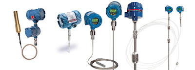
Drexelbrook Continuous and Point Level Control Products
Based on experience from of thousands of inquiries about level measurement, most questions boil down to "What is the best level measurement instrument for my application? That depends on quite a few application considerations, such as:
  • Will the measured media add coating to the probe?
  • Can the probe have contact with the media?
  • Are there explosion hazards?
  • What is the physical type of application, well, tank, open channel or floating roof tank?
This document can help deliver the perfect continuous level transmitter or level switches for your application.

Download a PDF version of the Drexelbrook Continuous and Point Level Control Selection Guide here, or view the embedded document below.

https://psi-team.com
800-223-1468