SIL Level Switch Is Specifically Designed for Floating Roof Tanks

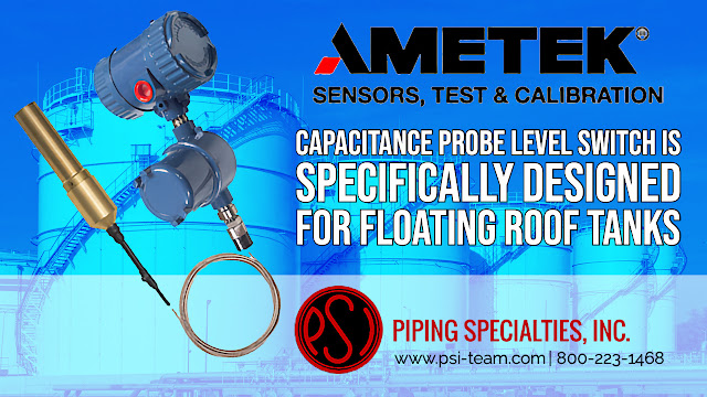
Capacitance Probe Level Switch Is Specifically Designed for Floating Roof Tanks

One of the most difficult and critical applications is measuring the high alarm or potential overfill condition on a floating roof tank containing liquid petroleum products such as crude oil or refined products such as fuel. It normally is comprised of a cylindrical steel tank equipped with an internal or external floating roof, that floats on the surface of the stored liquid. Floating roof tank systems are especially beneficial in eliminating the evaporative losses of the liquids. As opposed to a fixed roof tank there is no vapor space in the tank. This helps to reduce risk in highly explosive vapor environments. This is an extremely high cost of failure application, and one in which only the safest and most trusted products are accepted.

Safe operation of the tank farm relies on critical real time continuous level measurements of the liquids in the tank, as well as detecting when a high level condition exists. Products used in this application are typically required to meet the API 2350 Overfill Protection Standards, as well as SIL Safety Integrity Level performance standards to IEC 61508.

The challenges to reliably detect a high level condition on a floating roof tank are long sensor length requirements, and the variability of what is being measured. The floating roof may be dry in which case you need to detect the position of the physical metal roof. Or there may be a few inches of rain water or petroleum liquids on the roof. Measuring instruments need to determine very accurately, usually within a few millimeters, when the position of the floating roof has reached

The Drexelbrook SIL IntelliPoint capacitance probe level switch is specifically designed for Floating Roof Tanks (internal and external roofs) with a flexible brass level sensing probe. The level probe sensing element is field adjustable for lengths up to 15' (4.6 m). Electronics are designed to meet API 2350 Overfill Protection.

This level measurement system is specifically designed for spill prevention in floating roof tanks (internal and external roofs) using the IntelliPoint level switch with a flexible level sensing element for ease of installation (model 700-0005-595).

This level measurement system meets API 2350 regulations. It is ideal for use in safety related systems with requirements for functional safety for SIL2 in accordance to IEC61508-2, ed2, 2010 (Exida).

To prevent false alarms this level measurement system automatically recognizes and ignores coatings and is supplied with continuous self-test monitors circuits and sensing elements to detect faults.

A dual compartment housing separates the customer wiring from the sensing element and operating circuits. The encapsulated power supply/terminal block design eliminates the possibility of damage caused by moisture in the conduit.

The Floating Roof Tanks system comes with field adjustable lengths from 1' to 15' (0.3 to 4.6 m).

The system is based on our Manual Certify principle which allows the entire system to be manually tested without removing the sensor from the tank. The Manual Certify test checks that the Auto Verify circuits are operating and confirms the probe and cables are properly connected. Furthermore, the Manual Certify feature allows the electronics to sense changes in the probe that simulate contact with the media or floating roof. This provides the user with a method to ensure working performance without having to climb the tank.

No calibration or setpoint adjustments are required.

Key Features
  • Loop or Line Powered
  • Wetted Parts: 316SS 3/4" NPT Mounting, 3/16" FEP insulated flexible and adjustable cable, non-sparking brass sensor.
  • Automatic and local or remote manual test functions ensure proper system operation.
  • One system fits most floating roof tank applications, reducing field spans
  • Adjustable insertion lengths up to 15' (4,6m)
  • Excellent trip point accuracy over a wide range of medias and tank roof
Piping Specialties / PSI Controls
800-223-1468

High-performance and Resilient Seated Butterfly Valves for Commercial and Industrial Applications

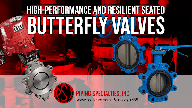
High-performance and Resilient Seated Butterfly Valves

A butterfly valve has a disc that is in the fluid flow path. In the most common style of butterfly valve, the disc revolves around a central axis, the stem, via a 90-degree arc from parallel to the flow direction (open) to perpendicular to the flow direction (closed).  Butterfly valves have a straightforward design with few moving components, making them simple to repair and maintain. The valve has four main parts: the body, the stem, the disk, and the seat. 


The butterfly disk is always in the flow path, but its thin profile has little effect on flow. Butterfly valves are popular because they provide tight shut-off, are available in various materials and sizes, and may be easily automated using a variety of quarter-turn electric and pneumatic actuators. 


You'll find butterfly valves in a wide range of industrial applications, from managing the flow of water to handling far more hazardous industrial fluids. Many industries use butterfly valves, including water treatment, chemical processing, pulp, paper manufacturing, food processing, power generation, etc. 


There are two primary classifications of butterfly valves:


  1. High-performance butterfly valves (HPBV)
  2. Resilient seated butterfly valves


High-performance butterfly valves include carbon or stainless steel bodies with Teflon seats and can withstand more significant pressures and temperatures.  Resilient seated valves usually feature ductile iron or aluminum bodies and operate at lower pressures and temperatures.


Butterfly valve bodies are available in two mounting styles: lug and wafer. Lug bodies include cast-in lugs with bolt hole designs that match pipe flanges. A wafer body valve does not have a mounting hole pattern, and mounting is facilitated by sandwiching the valve between two pipe flanges, with mounting bolts around the valve body. Wafer-style bodies are less costly. An advantage to lug body valves is their use as a dead-end valve, whereas wafer valves are unsuitable for this service.


The stem is a one or two-piece shaft that keeps the disk in place and provides the rotational torque that allows the disk to open and shut. The stem of resilient seated valves has protection from the process media by packing rings, allowing for a more cost-effective solution to regulate the valve's application to various potentially corrosive media. High-performance butterfly valve stems come into touch with process media and must be media suitable. 


The disk is the valve component that comes into direct contact with the process medium and regulates flow. Disks are available in various materials and optionally come with corrosion-resistant polymer coatings. Some butterfly valves include contoured disks that are carefully aligned with the stem to increase flow control, modify torque needs, or give the valve a longer life. 


A resilient seated valve closes via an "interference fit," which means the disk forces itself into the seat. The seat is the soft substance (polymer elastomer) including Buna-N and Nitrile, and should be specified depending on the process medium involved.


High-performance butterfly valves use an interference fit as well, but with significantly tighter tolerances, but also ensure tight seating with assistance from upstream pressure. PTFE or RTFE are the most often used materials for HPBV seats. Metal seats on HPBVs accommodate more significant pressure and temperature applications. 


Like other valves, butterfly valves have applications in which they outperform. To apply the optimum solution to your flow control applications, combine your process knowledge with your product knowledge with the application skills of a proven valve engineering professional. Contact Piping Specialties, Inc. for more information about industrial valves. Visit https://psi-team.com or call 800-223-1468.

Industrial Thermowell Process Connection Types


This video covers the common types of thermowell process connections. The styles are referred to by what their process connection is.

The types are threaded thermowell, a flanged thermowell, a welded or weld-in thermowell, and a sanitary thermowell.

Threaded thermowells are commonly used when thermowell removal occurs infrequently. These wells are typically threaded into a welded fitting widely referred to as a weldolet on the pipe or vessel. Typical installations include smaller pipes or vessels where corrosion is not an issue.

Flanged thermowells are the preferred well for applications that require frequent removal or replacement due to corrosion or other hazards. Flanged wells will bolt to a mating flange installed on the process piping. Typical installations include large pipes with high pressure and high corrosion.

Weld-in thermowells are welded directly to the pipe or tank and provide a high-quality connection. Because being welded in, their removal is not easy, and they should only be installed when quick access is not required, and corrosion is not an issue. Typical installations include very high temperature and high-pressure applications, for example, a steam line or other non-corrosive applications.

Sanitary thermowells are generally fitted with a Tri-clamp or other clean-in-place connection. These thermowells also have a smooth surface which allows for easy cleaning and prevents contamination of the process: typical installations include dairy, food processing, and pharmaceutical industries.

Piping Specialties / PSI Controls
800-223-1468

Water Cut Meters from Drexelbrook

Water (BS&W) Cut Meters

The water cut is the proportion of water collected in a well to the total liquids produced. As crude oil and hydrocarbons travel through a pipeline, a water cut meter monitors the amount of water (cut). BS&W is the amount of non-hydrocarbon contaminants, dirt (sediment), and water included in a crude oil shipment. The lower the BS&W, the better.  Water content determination and BSW have been a persistent and long-standing issue for the oil and gas industry.

Water cut meters measure the water cut (or BS&W) of oil flowing from a well,  a separator, crude oil transfer in pipelines, and tanker loading. 


Drexelbrook has been the global leader in capacitive-based water cut measuring. Drexelbrook has the industry's highest pressure and temperature ratings, and their capacitive probes can withstand pressures of up to 1500 psi and temperatures of up to 450°F. 

The Universal IV CM Series from Drexelbrook is a high-quality water cut meter with a range of 0-50 percent in light oil and 0-80 percent in heavy oil. 

The Universal IV CM Series builds upon Drexelbrook's expertise in RF Admittance, which enables the electronics to disregard paraffin and other coatings that accumulate on the probe. 

The Universal IV CM has a one-of-a-kind Cote Shield built into the Universal IV CM series and allows the instrument to disregard a pre-determined length of the sensing element. It contains a Perm-A-Seal sensing device that eliminates the need for epoxy coatings, which wear out and need costly maintenance. 

Field setup is available anywhere along the two-wire loop when using this water cut meter with Drexelbrook's HRTWin or the STExplorer PC program. 

Choose the Universal IV CM sensing element depending on pipe size, wetted portions, NACE requirements, and pressure/temperature requirements. Drexelbrook has a broad assortment of probes to suit almost any purpose. 

All water cut meters have a built-in LCD and keypad, are pre-calibrated at the manufacturer, and need just one point confirmation. 

The Universal IV CM water cut meter is intrinsically safe and approved for Class I, Division 1, and Zone 0 hazardous areas.

For more infomration in New England, contact Piping Specialties / PSI Controls. Call 800-223-1468 or visit https://psi-team.com.

Piping Specialties is Your Preferred Ball Valve Automation Specialist in New England

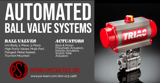
Ball Valve Automation

Piping Specialties / PSI Controls offer automated ball valve assemblies ranging from 1/2" to 48" that provide first-class quality, outstanding performance, and durability. The Piping Specialties valve automation shop inspects and tests every valve assembly before shipping from our facility. 

The valve automation department at Piping Specialties builds ball valve assemblies that save you substantial time on the job site. Automation specialists are highly trained, and all valve assemblies (both pneumatic and electric) receive functional testing before being shipped out to customers. Valve assembly inspection and validation occur before shipment using serialized and labeled quality assurance documentation. Assembly drawings, actuator sizing verification, and datasheets are available on request. 

Contact Piping Specialties / PSI Controls with your next automated ball valve requirement.


Piping Specialties / PSI Controls
https://psi-team.com
800-223-1468

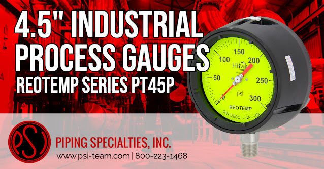
Extremely Durable 4.5 Inch Process Gauges

REOTEMP’s Series PT45P

The Series PT45P process gauge from REOTEMP endures corrosive atmospheres and media and pulsation and vibration; it is an extremely tough gauge designed for use in the process industries. The solid front and blowout back provide an extremely high level of user safety. Note: Install a diaphragm seal for applications that are highly corrosive, high-temperature, or subjected to rigorous usage.

Series PT45P Features

  • Safety Pattern Design
  • Solid Front/Blowout Back Safety Case
  • All Stainless Steel Internal Parts
  • Internal Overload and Underload Stops
  • Field Fillable Case
  • Micro-Adjustable Pointer with Floating Zero
  • ASME B40.100 Design
  • NACE MR-0175 and MR-0103 Compliant
Piping Specialties / PSI Controls
https://psi-team.com
800-223-1468