Showing posts with label Vermont. Show all posts

MOGAS Valve Selection Guide

For over 40 years MOGAS has designed and manufactured valves exclusively for the severe service market.  No leakage, limited maintenance and superior reliability make a MOGAS valve the easiest and most cost-effective valve to operate. Their portfolio of valve solutions lets you choose the design trim, materials, and coatings that provide your severe service application the best protection.

MOGAS is well-known in the power generation and process industries for solving critical problems that routinely plague these plants: leaking valves; seat erosion; blown packing; and the inability to isolate critical equipment.

Proudly made in the USA, each MOGAS valve carries an application-specific performance guarantee.


Piping Specialties, Inc - PSI Controls
800-223-1468
https://psi-team.com

Why Use LINK-SEAL®?


LINK-SEAL


LINK-SEAL® is a modular elastomer sealing system that creates a permanent, hydrostatic seal for almost any cylindrical object as it traverses a barrier. The modular LINK-SEAL ® seals are the primary technique for sealing tubes of any size continuously through walls and ceilings. Indeed, any cylinder-shaped item can be secured against water, soil or backfill material rapidly, readily and permanently.

LINK-SEAL® FEATURE AND BENEFITS


    LINK-SEAL
  • Install in up to 75% less time compared to lead-oakum joints, hand-fitted flashings, mastics, or casing boots.
  • Rated at 20 psig (40ft of head), which exceeds the performance requirements of most applications.
  • Designed for use as a permanent seal. Seal elements are specially compounded to resist aging and attack from ozone, sunlight, water, and a wide range of chemicals.
  • Standard fasteners have a two-part zinc dichromate and proprietary corrosion inhibiting coating. Corrosion resistant 316 stainless steel available for maximum corrosion protection.
  • NSF 61 and Factory Mutual Fire Approved materials available. Also carry a wide variety of approvals from various Federal agencies, associations, code groups, laboratories, and organizations.
  • Manufactured in an ISO 9001certified facility.
  • 16 sizes, color-coded EPDM, Nitrile, and Silicone elastomers may be used with various hardware options to match performance characteristics with service conditions.

LINK-SEAL® SPECIFICATIONS

  • Pressure resistant to 20psig (40 ft of head)
  • Standard  — EPDM – rubber (black)
  • Oil Resistant — Nitrile rubber (green)
  • Temperature resistant — Silicone rubber (gray)
  • Low Durometer for fragile pipe — EPDM rubber (blue) Shore 40 ± 5
  • Hardware Options - S316 Stainless Steel and Zinc Dichromate Coated Steel (1470 hr salt spray tested) hardware

LINK-SEAL® APPLICATIONS

Mechanical Contractors - Interior Piping Systems, Manhole Pipe Entry Seals, Waste Treatment Plants, Cased Road Crossings, Thermal Storage Systems, Fire Protection Wall Penetrations, Cased Railroad Crossings, Electrical Isolation of Pipes, Precast Concrete Vault Seals, Insulated Pipe Seals, Dual Containment Seals, Marine Applications, Noise Dampening, Flexible Sign & Pole Supports, Electrical Isolation of Pipe Supports, Mining, Pulp & Paper, Decorative Fountains, Pool Contractors, Electrical Contractors, Waste & Water Treatment, Telecommunications, Valve Pits, Refrigeration Buildings, Guard Post Assemblies, Power Generation Dams, Offshore Oil Rigs, High Pressure Tank Guards, Underground Steel Tanks, Precast Concrete Manufacturers, Perimeter Berm Installations Around Tank Farms, Flow Restrictions in Sewer Maintenance, Fluid Overflow Devices, Noise and Sway Dampener, Through Deck Fire Breaks, Bridge Construction, Septic Tank Installations, Coal Preparation Plants, Tunneling Operations.

For more information on LINK-SEAL® modular wall seals, contact Piping Specialties, Inc. Call them at 800-223-1468 or visit their web site at https://psi-team.com.

A-T Controls / TRIAC Valves and Actuators from Piping Specialties, Inc.


A-T Controls, Inc. designs, develops and manufactures valves, actuators and valve control products. Founded in 1994, A-T Controls currently operates out of the primary facility in Cincinnati, Ohio and another in Stafford, Texas with several sales offices throughout North America. Their products are used in virtually every industry including: Oil & Gas, Refining, Petrochemical, Chemical Processing, Pulp & Paper, Mining, Transportation, Food and Beverage, Pharmaceuticals, Marine, HVAC, and Power.

AT CONTROLS / TRIAC PRODUCTS:
  • Ball Valves
  • Butterfly Valves
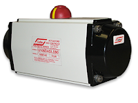
  • Rack & Pinion Pneumatic Actuators
  • Electric Actuators
  • Heavy Duty / Scotch Yoke Actuators
  • Floor Mounted Damper Drives
  • Gear Operators
  •  Limit Switches

For more information, contact Piping Specialties, Inc.
https://psi-team.com
800-223-1468

Plugged Chute Detection for Granular Materials

Intellipoint RF Admittance Plugged Chute Detector
Detecting plugs in granular material conveying chutes is difficult due to the heavy, abrasive materials and dusty, coating nature of the environment. Many technologies used to detect material movement in chutes have considerable downside. For instance, regulatory requirements and source disposal problems make nuclear gauges an unappealing choice, insertion type sensors are quickly damaged by falling material, microwave sensors require two mounting windows to operate, and vibrating chute walls can damage electrical components.

A better alternative is the Drexelbrook Intellipoint RF Admittance Plugged Chute Detector. Its design allows for the reliable detection of a plugged chute, reducing costly downtime and material spill over.

The Drexelbrook plugged chute detector, also known as a blocked chute switch, reliably detects the presence or absence of bulk solids material flowing through chutes in an economical way without sacrificing flow speed. If process material stops flowing due to a plugged condition, the flush mounted capacitance sensing element will alarm, allowing further action to occur (alerting an operator, shutting down a conveyor belt, etc.). The Cote shield circuitry ignores even heavy coatings, and the flush mounted sensing element does not interfere with material flow. There are no moving parts to wear or jam, and thus, it requires virtually no maintenance. In fact, the Intellipoint Mean Time To Failure (MTTF) is calculated to more than 110 years!

There are no regulatory requirements with the adoption of the Intellipoint, and system electronics can be mounted remotely to eliminate vibration concerns. Due to the rugged sensor design this point level switch is ideal for coal, wood chips, ores and powders. This point level switch automatically recognizes and ignores coatings to prevent false alarms and, as it is flush mounted through a chute wall, nothing protrudes into the chute to interfere with or obstruct material flow.

Choosing the Intellipoint provides reliable detection of plugged chutes that will keep your plant running smoothly and virtually eliminates spills occurring due to plugged conditions.

Key Features
  • Curved and flat sensors are available
  • DPDT relay dry contacts at 5A, 120VAC
  • Less maintenance than other technologies; no moving parts to hang up or wear out
  • Uses Drexelbrook PML series electronics
  • Supply voltage: 19-250 VAC, 18-200 VDC, Auto-detecting without jumpers
For more information, contact Piping Specialties, Inc. by calling 800-223-1468 or by visiting https://psi-team.com.

Mounting and Adjusting a Rack & Pinion Actuator


A-T Controls is a global leader in the design, manufacturing and sale of manual & automated process valves for all types of industries.

This video details the steps required to mount and adjust a TRIAC rack and pinion actuator to an AT Controls ball valve.

Piping Specialties sells, services, and automates A-T Controls valves and TRIAC actuators in New England.

For more information, contact Piping Specialties by calling 800-223-1468 or visiting https://psi-team.com.

Guide to Industrial Refractometer Applications

Industrial refractometer
(K-Patents)
As a general rule, refractometers measure the concentration of any dissolved material in a liquid. A typical measured medium is a binary solution, but it can also be a mixture of more than two components. In multi-component solutions this is a checksum; if one of the components is wrong, the overall refractive index value changes.

The potential applications in different industries are countless. Although the manufacturing process, environment and processing medium vary from industry to industry, all basic unit operations and control strategies are roughly the same despite of the end product.


Applications discussed in the application guide include:
  • Crystallizers
  • Reactors
  • Evaporation
  • Ultrafiltration
  • Reverse Osmosis
  • Spray Dryers
  • Dissolving Tanks
  • Solid / Liquid Extraction
  • Cooking Processes
  • Ion Exchangers
  • Absorbers and Wet Scrubbers
  • Distillation
  • Interface Detection

For more information about the application of industrial refractometers in manufacturing processes, contact Piping Specialties / PSI Controls by calling 800-223-1468 or by visiting their web site at https://psi-team.com.

Basics of Industrial Globe Valves

Exploded view of globe valve
(courtesy of Conval)
Globe valves work differently when compared to gate valves, ball valves, butterfly valves and plug valves in process control applications. They are primarily used to control the flow inside pipes, and are popular in a wide variety of industries. Globe control valves are ideal in situations where precise control is required. They are used to regulate flow in pipelines with a high degree of accuracy by regulating a pressures drop created in the valve body that allows the fluid to pass through the passageway (port) in the valve body. The control valve stem provides linear motion to control flow, opening and closing the valve by changing the distance between valve disc and seat. The flow in the pipeline changes according to the position of the disc lifting from the seat. The movement is controlled through the use of manual operators, or through the use of electric or pneumatic actuators.

Applications of Globe Valves

Globe valves are used in many different industries, but particularly in the petrochemical and power generation industries on fuel oil pipes, chemical feed systems, steam pipes, as well as cooling water and feedwater systems.  Other industrial applications of globe valve include boiler, main steam vents, and turbine lube oil systems.

Pros

Globe valves have many advantages that make them preferable over other valve designs. Globe control valves have excellent shut-off and throttling capabilities. In addition, globe valves are easy to maintain and repair compared to other valves.

Cons

Internal view of globe valve
(Conval)
Globe valves have also certain shortcomings. For instance, globe valves have an S-shaped flow pattern (as opposed to a straight-through flow pattern) which creates a significant pressure drop making them unsuitable for applications constant pressure is required.  Another shortcoming of the globe valves is they generally require greater torque to open and close, requiring larger actuators to properly seat the valve.

For more information on industrial globe valves, or any type of industrial valve, contact Piping Specialties, Inc. by calling 800-223-1468 or by visiting https://psi-team.com.

MOGAS Critical Service Valves Fire Tested to API 607 and API 6F3


This video explains the MOGAS approach to fire testing their severe service ball valves to API requirements.
  • API 607, 7th Ed. Fire Test for Quarter-turn Valves and Valves Equipped with Nonmetallic Seats
  • API 6FA, 3rd Ed. Specification for Fire Test for Valves
Piping Specialties, Inc.
800-223-1468

Hyspan Series 1500 Laminated Bellows Expansion Joints

Pipe expansion or contraction resulting from temperature changes is independent of line size; however, the bellows elements of small diameter expansion joints have less ability to absorb motion than larger sizes because of restrictions on the corrugation size. Recognizing these shortcomings, Hyspan® developed Series 1500 Laminated Bellows Expansion Joints for applications that involve axial motion.

The bellows elements are designed with up to four individual thicknesses or laminations of precision stainless steel foil. This design procedure combines the high flexibility of thin material while providing the pressure resistance of multiple laminations. 

As a comparison, a bellows made from four plies of 0.008" thick material has the same pressure rating as a single thickness of0.016" thick, but the laminated construction will deflect twice as much and requires only one-half the force to compress.


Piping Specialties, Inc.
https://psi-team.com
800-223-1468

The Pratt Industrial TE Series Triple Offset Butterfly Valve

The Triple Offset Butterfly valve has been designed to answer the industries demand for an alternate solution to gate valves and ball valves where weight, space,  performance, and the ability to modulate to the process flow were an issue.

Pratt Industrial Triple Offset Butterfly Valves are from the family of quarter-turn valves. This valve is designed and manufactured to meet API 609 and ASME B16.34 specifications.

Applications
  • Block/Isolation
  • Modulating; manual, pneumatic, or electric motor operators.
Industries
  • Refinery
  • Chemical
  • Petrochemical
  • Power
  • Steam Generation
  • Water/Waste Water Treatment


What Are LINK-SEALS?

Considered to be the premier method for permanently sealing pipes of any size passing through walls, floors and ceilings, LINK-SEALS® are a modular, elastomer sealing system that creates a permanent, hydrostatic seal for nearly any cylindrical object as it passes through a barrier. With LINK-SEALS®, any cylindrical object may be quickly, easily and permanently sealed against the entry of water, soil or backfill material.

Why You Should Use LINK-SEALS®:
    LINK-SEALS
  • Install in up to 75% less time compared to lead-oakum joints, hand-fitted flashings, mastics, or casing boots.
  • Designed for use as a permanent seal. Seal elements are specially compounded to resist aging and attack from ozone, sunlight, water, and a wide range of chemicals.
  • Rated at 20 psig (40ft of head), which exceeds the performance requirements of most applications.
  • NSF 61 and Factory Mutual Fire Approved materials available. Also carry a wide variety of approvals from various Federal agencies, associations, code groups, laboratories, and organizations.
  • Standard fasteners have a two-part zinc dichromate and proprietary corrosion inhibiting
    LINK-SEALS
    coating. Corrosion resistant 316 stainless steel available for maximum corrosion protection.
  • Manufactured in an ISO 9001certified facility.
  • 16 sizes, color-coded EPDM, Nitrile, and Silicone elastomers may be used with various hardware options to match performance characteristics with service conditions.

For more information about LINK-SEALS®, contact Piping Specialties, Inc.
https://psi-team.com
800-223-1468

Jet Pump (Eductor) Theory of Operation

Jet Pump (Eductor)
Jet Pump (courtesy of Emerson Penberthy)
Also known as eductors, jet pumps operate on the principles of fluid dynamics. An operating fluid medium, which is referred to as the MOTIVE, placed under pressure, enters the inlet and is forced through the nozzle where it is converted into a high-velocity stream. This high-velocity stream decreases the pressure in the suction chamber, creating a partial vacuum that draws the suction material into the chamber where it is entrained by the motive medium. Once the SUCTION stream is drawn in, shear between the motive medium and the transported material causes both media to be intermixed and pumped out the DISCHARGE outlet, dispelled at a pressure greater than that of the SUCTION stream but lower than that of the MOTIVE. This basic principle of fluid dynamics is what makes jet pumps work.

MOTIVE:

This function is the power phase of the pumping operation. At this stage, the velocity of the motive medium increases as it passes through a nozzle. This phase of the pumping operation takes advantage of the kinetic properties of the motive medium, whether it is liquid, steam or gas. Because of this, design differences may exist within the motive connection of the jet pump.

For instance, jet pumps with liquid motives use a converging nozzle, since liquids usually cannot be compressed. On the other hand, jet pumps with gas or steam motives use converging/ diverging nozzles to achieve transsonic flow velocity. The critical flow paths of all jet pumps are machined smoothly with no abrupt turns or steps in order to produce the most efficient flow during the motive function. Without this direct flow design and smooth interior surface, the jet pump would not operate at peak efficiency.
Jet Pump (Eductor) Theory of Operation
Click for larger view.
This connection is where the pumping action takes place. The high velocity stream of the motive causes a drop in pressure in the suction chamber. This allows pressure in the suction vessel to push a liquid, steam or gas into the suction chamber of the jet pump. This, in turn, is entrained by the high-velocity motive stream emerging from the inlet nozzle.

DISCHARGE:

As the motive flow combines with the suction medium, some kinetic energy of the motive is transferred to the suction, mixing and discharging at a reduced pressure. The amount of pressure that can be recovered depends on the ratio of motive flow to suction flow, plus the amount of suction pressure built up in the suction vessel. Kinetic energy is converted back to pressure as the mixed media passes through the diverging taper and is discharged from the pump.

For more information about jet pumps and their applications, contact Piping Specialties, Inc. by calling 800-223-1468 or by visiting their web site at https://psi-team.com.

Direct Acting and Pilot Operated Pressure Relief Valve Operation


relief valve
Here is a clear and well illustrated tutorial video demonstrating the operational principals of pilot and direct acting pressure relief valves.

There are many available configurations of pressure relief and safety valves, each tailored to accommodate a particular set of application criteria. Understanding how these valves work is important to their proper selection and application to industrial processes and their control.

Safety mindedness is critical for these applications, and you should always talk to an experienced applications expert before specifying or installing these products. Product performance and selection information, as well as application assistance, is available from your local product specialists.

Piping Specialties, Inc.
https://psi-team.com
800-223-1468

Problems with Measuring Level of High Density Pulp Stock

Level Measurement in Pulp Stock
Level Measurement in Pulp Stock has posed problems for a wide range of level measurement technologies. In most pulp mills this is the most challenging application on site.

The environment in the high-density pulp tank is very corrosive to most common metals and the clouds of dense steam vapors that rise from the stock and foaming surface of the level are a constant source of signal loss for many non-contact technologies.

Due to the size of the vessel and density of the stock, mechanical devices are typically short  lived.Stock coatings that form on all interior surfaces add additional mechanical stress and the pulp coating deposits can adversely affect accurate level measurement performance.

One of the challenges of a level measurement device is to control the level in the stock tank, thereby helping to control the average pulp density by controlling the speed of the pump.The response time of the level measurement system is critical in controlling the pump speed and reducing pump oscillations and surges that will eventually reduce the life of the pump.Too slow of a response from the level instrument will allow the level to rise above it ’s optimum density level and cause excessive loading and wear on the pump.


Piping Specialties, Inc.
PSI Controls
https://psi-team.com
800-223-1468


Types of Pneumatic Valve Actuators

Scotch-yoke actuators
Scotch-yoke actuators (Morin)
Pneumatic valve actuators all provide the same function:  They convert air pressure to rotational

movement and are designed to open, close, or position a quarter-turn valve.  These include ball valves, plug valves, butterfly valves, or other types of 90 degree rotational valves.

The basic design variations of pneumatic valve actuators are as follows:

  • Rack and pinion
  • Scotch-yoke
  • Rotary vane

Let's review each of these in detail:

Rack and Pinion Actuators

Rack and pinion actuator
Rack and pinion actuator (Unitorq)
These actuators are sometimes referred to as, “lunch box,” because they, well, look like a lunch box. This actuator uses opposing pistons with integral gears to engage a pinion gear shaft to produce rotation. They are usually more compressed than a scotch yoke, have standardized mounting patterns, and produce output torques suitable for small-to-medium sized valves.  Rack and pinion nearly always include standard bolting and coupling patterns to directly attach a valve, solenoid, limit switch or positioner.  One of their features include several smaller coil springs mounted internally, which provide the torque to return the valve to its starting position.

Scotch-yoke Actuators 

Scotch-yoke actuators
Scotch-yoke actuators internal view.
These actuators come in a multitude of sizes, but are usually used on larger valves because they can produce a very high torque output.  They employ a pneumatic piston mechanism to transfer movement to a linear push rod.  That rod, in turn, engages a pivoting lever arm to provide rotation. Spring return units have a large return spring module mounted on the opposite end of the piston mechanism working directly against the pressurized cylinder.

Rotary Vane Actuators 

Rotary vane actuators
Rotary vane actuator animation.
These actuators are usually used when the application requires a significant space savings.  They take up less space when comparing size-to-torque with rack and pinion and scotch yoke. Rotary van actuators also benefit from a reputation of longevity.  They contain fewer moving parts than other types of pneumatic valve actuators.  Rotary vane actuators use externally mounted, helically wound "clock springs" for their spring return mechanism.

These style of valve actuators can all be secured with direct acting or spring return versions. Direct acting actuators use the air supply to move the actuator in both directs (open and close). Spring return actuators, as the name describes, uses springs to move the actuator back to its "resting" state. Converting a version from direct acting to spring return is done through simple modifications, typically just adding an external spring module, or removing the end caps from rack and pinion actuators and installing several coil springs.

When considering the choice of pneumatic valve actuators, your decision comes down to size, power, torque curve and the ease of adding peripherals. To ensure that your valve actuation package will be optimized for safety, longevity, and performance, the advice of a qualified valve automation expert should be sought out. That expert will be able to help you with the best selection of the appropriate valve actuator for any quarter turn valve application.

For more information on valve actuation, contact Piping Specialties, Inc.
https://psi-team.com
800-223-1468

Understanding Differential Flow Measurement


The differential flow meter is the most common device for measuring fluid flow through pipes. Flow rates and pressure differential of fluids, such as gases vapors and liquids, are explored using the orifice plate flow meter in the video below.

The differential flow meter, whether Venturi tube, flow nozzle, or orifice plate style, is an in line instrument that is installed between two pipe flanges.

The orifice plate flow meter is comprised the circular metal disc with a specific hole diameter that reduces the fluid flow in the pipe. Pressure taps are added on each side at the orifice plate to measure the pressure differential.

According to the Laws of Conservation of Energy, the fluid entering the pipe must equal the mass leaving the pipe during the same period of time. The velocity of the fluid leaving the orifice is greater than the velocity of the fluid entering the orifice. Applying Bernoulli's Principle, the increased fluid velocity results in a decrease in pressure.

As the fluid flow rate increases through the pipe, back pressure on the incoming side increases due to the restriction of flow created by the orifice plate.

The pressure of the fluid at the downstream side at the orifice plate is less than the incoming side due to the accelerated flow.

With a known differential pressure and velocity of the fluid, the volume metric flow rate can be determined. The flow rate “Q”, of a fluid through an orifice plate increases in proportion to the square root the pressure difference on each side multiplied by the K factor. For example if the differential pressure increases by 14 PSI with the K factor of one, the flow rate is increased by 3.74.

Piping Specialties, Inc. / PSI Controls
800-223-1468
https://psi-team.com

The Azbil AX Series of Vortex Inline Flow Meters

Azbil AX Series
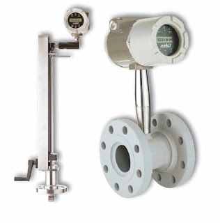
The AX Series of Vortex inline flowmeters measure flows of liquid, gas, and steam by measuring the rate at which vortices are alternately shed from a bluff body; this rate has been shown to be directly proportional to the flow velocity.

As flow passes a bluff body in the stream, vortices create pressure differentials which are measured by a piezoelectric crystal sensor, which converts these pulses into electrical signals. The meter uses an all-welded sensor design to create a strong unit and minimize potential leakage.

The Azbil AX Series can be configured to measure anything from simple volumetric flow of liquids and saturated steam up through multivariable measurements, including mass flow rate, pressure, temperature and density of liquids and steam.

Insertion style vortex meters measure fl ow by detecting the local velocity at a strategically located position within the pipe. Using local velocity, calculated by measuring the rate at which vortices are alternately shed from a bluff body within the sensor, the Azbil AX2300 uses parameters such as fluid type, pipe size, and Reynolds number to calculate accurate measurements.

Download the Azbil AX Series Vortex Flow Meter brochure here.


Using Link-Seal in Combination with Century-Line Sleeves or Cell-Cast Disks for Sealing Pipe Penetrations when Pouring Walls, Floors or Ceilings


Sealing pipes passing through concrete barriers can be one of the really tough challenges confronted by designers and installers of any piping system. But there's a way to simplify the whole process. All it takes is the system approach.  Link-Seal in combination with Century Line sleeves makes for a dynamic combination.  Just what you need to quickly and easily seal any cylindrical object passing through concrete poured walls, floors, and ceilings.

Link-Seal is a flexible belt of interconnected rubber links used to seal the void area or annular space between a cylindrical pipe and round wall opening. Be it a steel sleeve, plastic sleeve, or poured hole, installation is easy. The belt is simply wrapped around the pipe connected and secured by tightening the bolt heads moving clockwise around the seal. Pressure plates on each side of the link applied the compression necessary to expand the rubber. As the bolts are tightened, the links enlarge from a free to an expanded state, transforming the belt of separate links into a hydrostatic seal capable of holding in excess of 20 PSIG with a safety factor of 5 to 1. In the laboratory under controlled conditions, Link-Seal has been successfully tested to 100 PSIG and above.  In addition, accelerated aging tests have shown Link-Seal to be capable of providing maintenance-free service over performance life cycles estimated at 40 years or more.

In the real world, Link-Seal improves overall system reliability by effectively dampening the damaging effects of vibration.  Link-Seals reduce fatigue on pipe welds, flanges and threaded connections. As an added bonus, they may also be used to isolate stray electric current passing through pipes and casings. Applications for Link-Seal are almost infinite. In fact, any cylindrical object may be quickly easily and permanently sealed as they pass through barriers of all kinds.

For more information on Link-Seal, contact:
Piping Specialties, Inc.
https://psi-team.com
800-223-1468

What Are Trunnion Mount Ball Valves?

Trunnion ball valve design. Trunnions highlighted.
Ball valves are well understood in process control and industrial piping systems. Their simple 1/4 turn operation, compact form factor, bidirectional sealing, and tight shutoff make them a very popular choice for a wide range of applications.

Although there are many varieties of seat designs, body styles, and flow patterns, ball valves can be separated in to two main groups, distinguished by a primary design element - the mounting method of the valve ball.

The two groups are:
  • Floating ball
  • Trunnion mounted ball
Floating ball valves use the body and valve seats to position and hold the ball in the media flow path, allowing the flow force to lodge the "floating" ball firmly against the downstream seat. In this style, the ball is not mechanically held in place, thus the term "floating". Floating ball valves are, in general, limited to applications with smaller sizes and lower pressure ranges because, at some point, the fluid pressure on the ball may exceed the seat and trim's ability to hold the ball properly in place.

Trunnion mount valves, on the other hand, employ a "trunnion" in their design. A trunnion is a pin, or a pivot, forming one of a pair on which ball is mechanically connected and supported. The valve shaft and the trunnion connect at the top and bottom of the valve and create the vertical axis of rotation for the ball. The trunnion also prevents the ball from moving or shifting with changing pressures.

Due to their structural integrity, trunnion mount ball valves are generally well suited for all pressure ranges and valve sizes. Their design is used by many manufacturers for severe service. They provide excellent sealing properties over an extensive range of temperatures and pressures. Trunnion mount valves are available in both full and reduced bore designs with a wide range of materials, sizes, and pressure classes offered. The vast range of sizes, styles, pressure classes, and materials together with conformance to ANSI, API, and NACE specifications make these valves suitable for virtually all industrial, petrochemical, refinery, and oil and gas services. Finally, there may be an advantage to actuate trunnion ball valves due to lower torque requirements compared to similar floating ball valves whose torque increases with increasing flow pressure.

For more information on floating ball or trunnion mount ball valves, contact Piping Specialties, Inc. at 800-223-1468 or visit https://psi-team.com.

Process Refractometers Used in Black Liquor Recovery Boilers

recovery boiler
The recovery boiler plays a central role in the chemical cycle of a modern pulp mill. The recovery boiler is a chemical reactor, which is used for recovering chemicals from spent kraft liquor and generating energy at the same time.

In the recovery boiler, the organic matter is burned. The dry solids liquor content required for firing is at least 60 %, but preferably more than 65 %. Black liquor is concentrated by evaporating water from the liquor. When the concentration of black liquor is maximized, so is the energy production. Before entering the burners, sodium sulfate decahydrate, or glauber salt, is added to cover chemical losses.

Application
Black liquor
Chemical curve: R.I. per Black
liquor Conc% at Ref. Temp. of 20 ̊C

The liquor should have a high content of combustible dry solids in order to minimize flue gas emissions and maximize boiler efficiency.

Too low concentration of dry solids fed to the burners may result in a steam explosion with consequent damage or destruction to the boiler. Therefore, it is essential to utilize a refractometer to monitor the black liquor feed to the recovery boiler to ensure a safe operation.

Instrumentation and installation

The K-Patents Digital Divert Control System DD-23 complies strictly with all recommendations of the Black Liquor Recovery Boiler Advisory Committee (BLRBAC).

The DD-23 system includes two SAFE-DRIVE Process Refractometer sensors in the main black liquor line, two indicating transmitters and a divert control unit in an integrated panel.

The sensors are installed using K-Patents patented SAFE-DRIVE Isolation valve. This allows for safe and easy insertion and retraction of the refractometers under full operating pressure, without having to valve off the liquor piping or having to shut down the process. The SAFE-DRIVE Isolation valve contains a steam wash system for automatic prism cleaning. The system contains a SAFE-DRIVE Retractor Tool SDR-23 for safe sensor insertion and retraction.

For more information about refractometers used on blacl liquor recovery boilers, contact Piping Specialties by calling 800-223-1468 or visit https://psi-team.com.